Jupyter ROS: embedding ROS Data Visualization on Jupyter notebooks
.
What we are going to learn
Learn how to embed ROS data visualization inside a Jupyter notebook.
List of resources used in this post
- ROSject with all the code and simulation: http://www.rosject.io/l/d4b0981/
- Jupyter ROS, the tool that allows us to see ROS data in the notebooks: https://github.com/RoboStack/jupyter-ros
Opening the ROSject
In today’s post, we are going to learn how to see ROS Data inside a Jupyter Notebook using the Jupyter ROS package. Let’s start by clicking on the ROSject link (http://www.rosject.io/l/d4b0981/). You should now have a copy of the ROSject.
Now, let’s open the notebook by clicking the Open ROSject button.
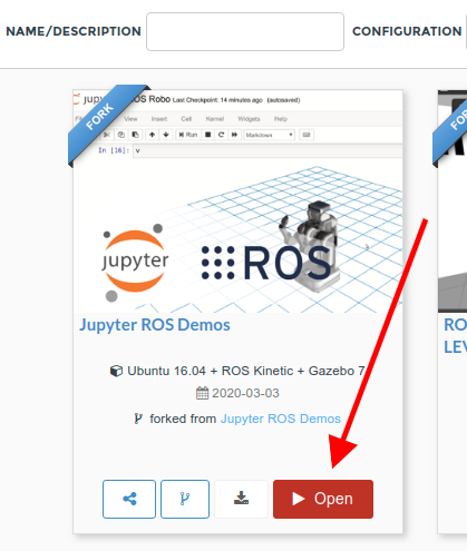
Open ROSject – Juypter ROS Demo on ROSDS
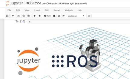
When you open the ROSject, a default notebook will be automatically open with the instructions on how to show ROS Data in Jupyter.
The demos are possible thanks to the Jupyter-ROS project developed by Wolf Vollprecht from Quantstack. All credit goes to him and his team.
What follows is the list of ROS enabled notebook demos that work off-the-shelf by using the ROSDS integrated simulations. The original notebook demos were created by Wolf. In The Construct, we only have added the explanations required to understand the code and launch the simulations, so you can have a live demo without having to install and configure your computer.
The ROSject provides everything already installed and configured. Hence, you don’t need to install Jupyter ROS, you only need to learn how to use it… and then use it! (for instructions about how to install on your own computer, please check the author’s repo)
You can freely use all the material from the ROSject to create your own notebooks with ROS.
List of demos
When you open the notebook, the list of demos you have are:
- ROS 3D Grid: about how to include an interactive 3D grid inside a notebook.
- ROS Robot: about how to add the robot model inside the 3D grid
- ROS Laser Scan: about how to show the robot laser on the 3D grid.
- ROS TEB Demo: about how to add interactive markers to the 3D viewer
Where to find the notebooks inside the rosject
All the notebook files are contained in the ROSject.
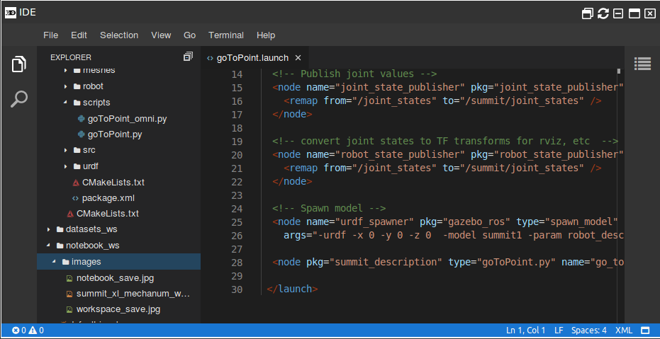
In order to see the actual files, use the IDE (top menu, Tools->IDE). Then navigate through the folders up to notebook_ws->notebooks.
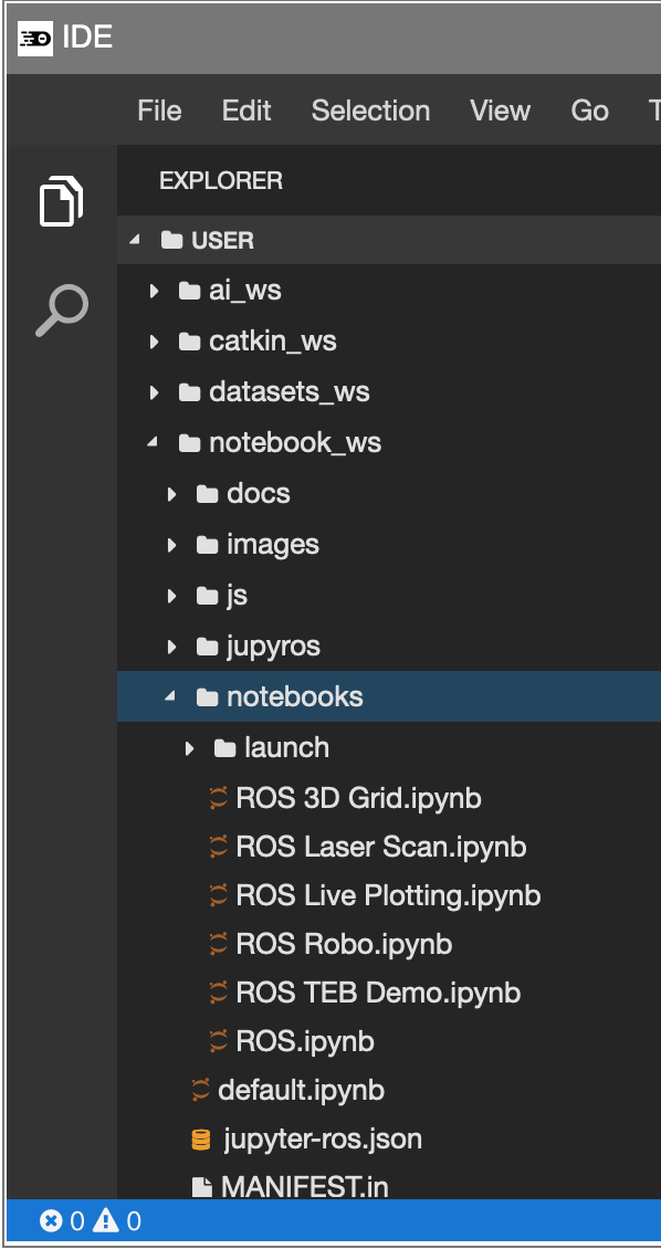
Jupyter ROS – List of files in ROSDS
How to modify the provided notebooks directly in ROSDS
ROS Laser Scan demo
In the notebooks of the ROSject, we have four demos, but in this post, we are going to show only how to show Laser Scan in the notebook to make things simpler.
In order to get this working, we are going to use the simulation of a Turtlebot.
Remember that you have to have the ROS Bridge running in order for Jupyter ROS to work. If you haven’t started it yet, launch it now.
- Go to the ROSDS TAB in your browser
- On the top menu, select Tools->Shell
- On the opened shell type the following command:
roslaunch ~/notebook_ws/notebooks/launch/bridge.launch --screen
Launching the simulation
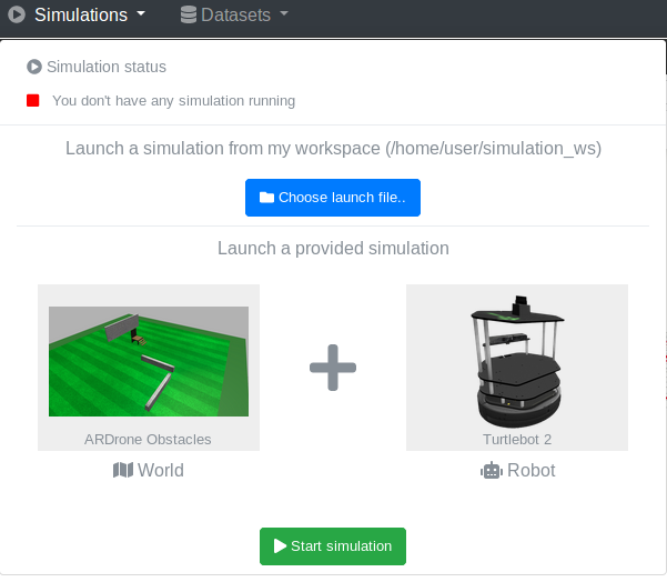
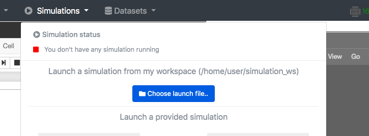
- Go to the ROSDS TAB and go to its top menu.
- Select Simulations.
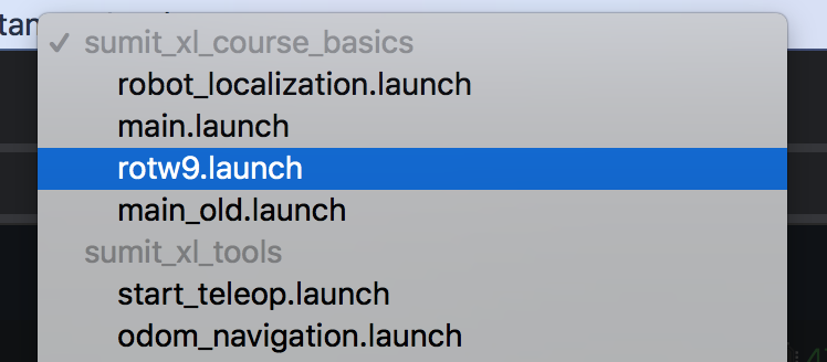
- On the panel that appears, click on the label that says
Select world. - Then on the drop-down menu that appears, move down until you see the
AR Drone world. - On the panel that appears, click on the label that says
Select robot. - Then on the drop-down menu that appears, move down until you see the Turtlebot 2.
- Click on it and then press
Start simulation
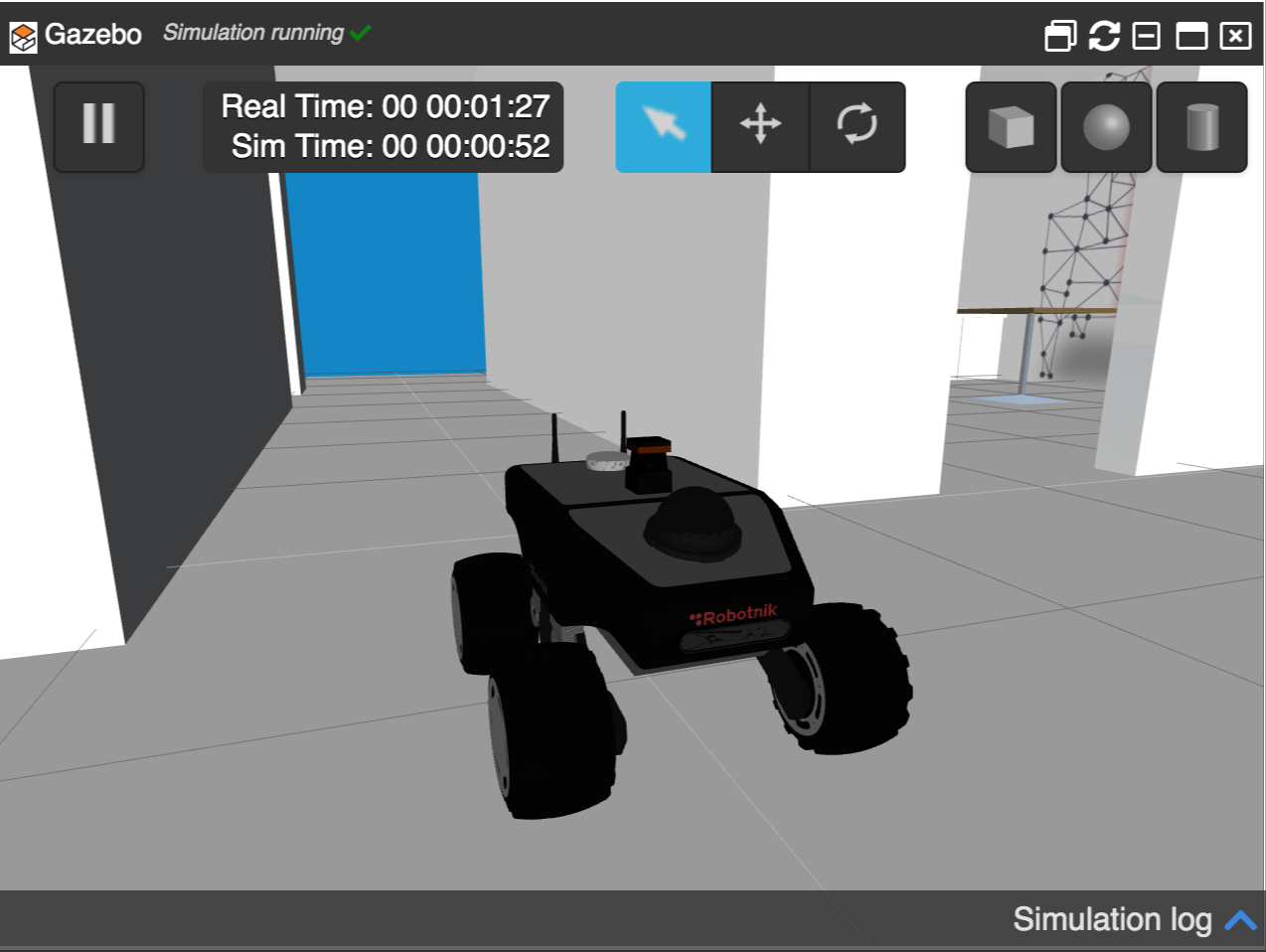
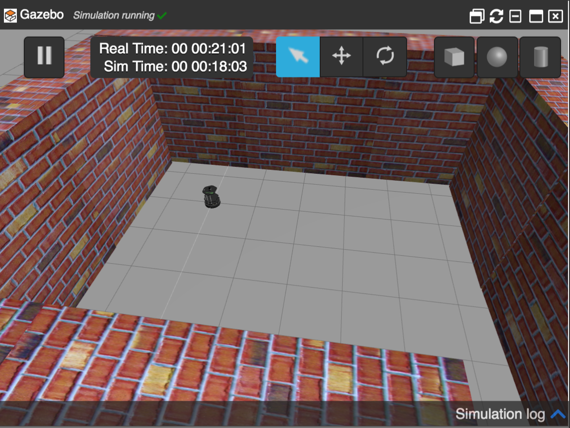
Turtlebot in a green area in ROSDS
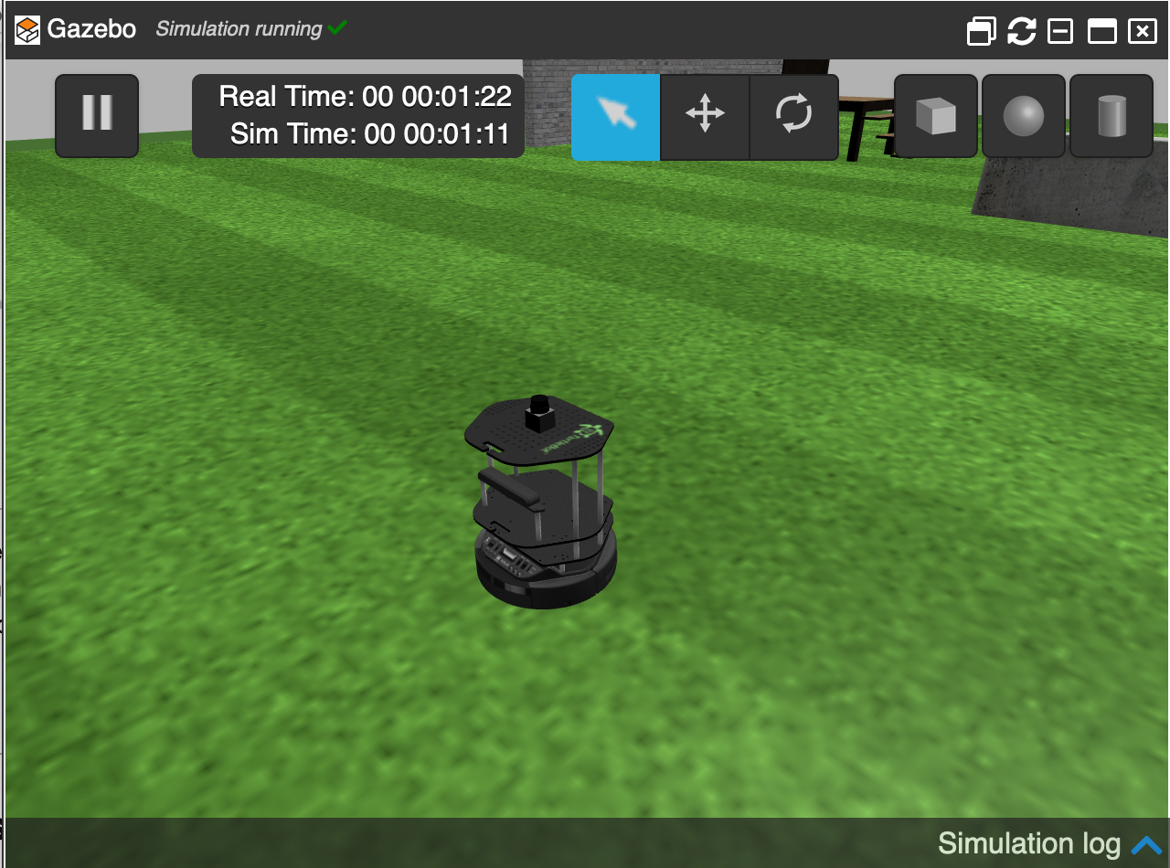
Turtlebot opened in a green area in ROSDS
First, Start the demo
First, import the required classes from Jupyter ROS.
Shift+Enterto activate the Python code.IMPORTANT: the import of such a class can take some time!. You will know that the code is still running because the number on the left of the cell has changed to a * character. Do not move to the next step until the * is gone.
try:
    from sidecar import Sidecar
except:
    pass

from jupyros import ros3d
Second, create an instance of the viewer, connect to ROS and get the TF
Shift+Enterto activate the Python code.
v = ros3d.Viewer()
rc = ros3d.ROSConnection()
tf_client = ros3d.TFClient(ros=rc, fixed_frame='/base_footprint')
Connect to the topic of the laser
Shift+Enterto activate the Python code.laser_view = ros3d.LaserScan(topic="/kobuki/laser/scan", ros=rc, tf_client=tf_client)
Fourth, get the 3D grid and the robot model
Click on the next cell and then press Shift+Enterto activate the Python code.
g = ros3d.GridModel()
import os
urdf = ros3d.URDFModel(ros=rc, tf_client=tf_client, path=os.environ.get('JUPYROS_ASSETS_URL', 'http://localhost:3000'))
v.objects = [g, laser_view, urdf]
Fifth, visualize everything
Click on the next cell and then press Shift+Enterto activate the Python code
try:
    sc = Sidecar(title='Sidecar Output')
    with sc:
        display(v)
except:
    display(v)
Sixth, change the visualization style (if required)
Click on the next cell and then press Shift+Enterto activate the Python code.
v.layout.height= '1000px'
g.color = '#CCC'
laser_view.point_size = 0.1
laser_view.static_color = "green"
Move the robot around and watch the laser change!
Open a new shell (Tools -> Shell) and type the following command to make the robot move around:
rostopic pub /cmd_vel geometry_msgs/Twist "linear:
  x: 0.2
  y: 0.0
  z: 0.0
angular:
  x: 0.0
  y: 0.0
  z: 0.3"
That is it. If you did everything ok, you should see the robot moving around in the jupyter notebook.
Learn more about Jupyter ROS
Youtube video
So this is the post for today. Remember that we have the live version of this post on YouTube. If you liked the content, please consider subscribing to our youtube channel. We are publishing new content ~every day.
Keep pushing your ROS Learning.

![[ROS Mini Challenge] #7 – make a robot follow another robot](https://www.theconstruct.ai/wp-content/uploads/2020/02/rotw7-sim2.png)