In this video we’ll improve our URDF code of the robotic manipulator using XACRO. From the URDF model, finish the robot, creating all joints and links and visualize it using RViz. Up to the end of the video, we will have the model finished, a launch file to visualize it and a RViz and some MACROs to help you in the development of the robot.
In this video we are going to see how to write robot Poses into a file. This will allow you to keep track of the different positions that a mobile robot is in while it is moving.
▸ Get the code of the video by clicking on this link: https://goo.gl/DBdKoz (You need an account on RDS. Once you click on the link, the whole code will appear on your RDS account ready to use)
Follow these steps to reproduce the project as shown in the video
Create a new project. Choose a informative name and add some description in the description field. (for this tutorial we are using project name poses_to_file)
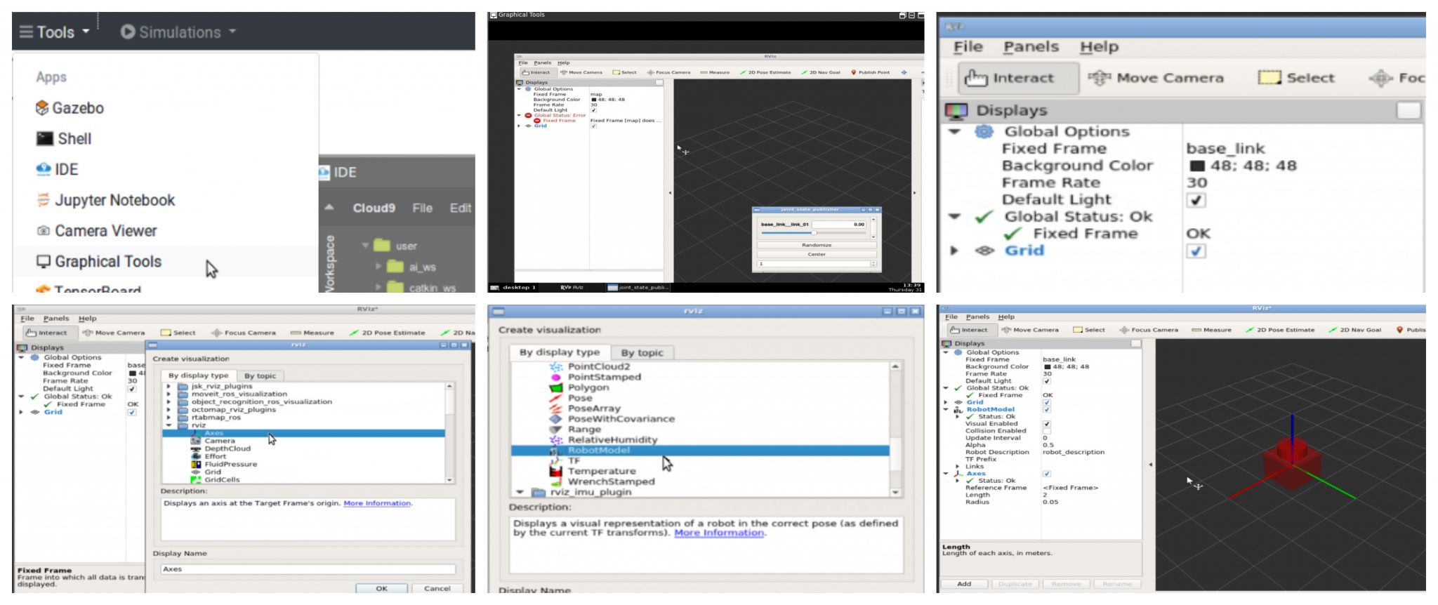
Open the project. This will being you to the RDS environment with two menu options Tools and Simulations
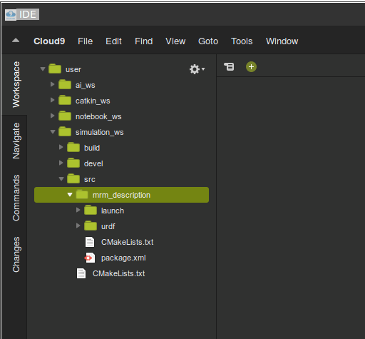
Start an IDE by selecting IDE option from the Tools. IDE is a very useful tool, it lets you navigate and edit files/directories. Try navigating around and verify that the directory layout of the project is as shown below:
Note that we use simulation_ws directory to contain all files related to simulations.
Those files not related to simulations will go to catkin_ws (like python scripts, launch files etc)
Step 2
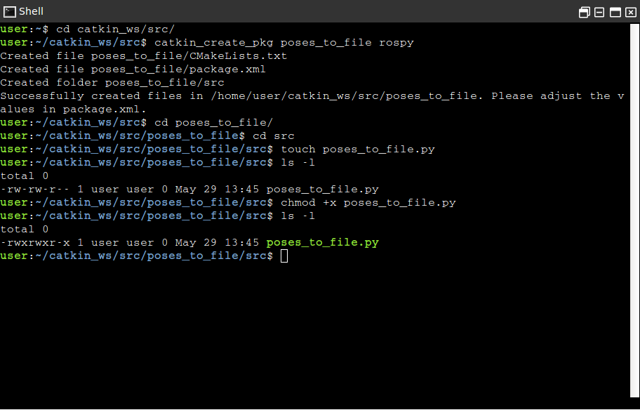
We will create a new catkin project inside the catkin_ws/src directory
$ cd catkin_ws/src catkin_create_pkg poses_to_file rospy
Next we will create a python script to write the poses to the file. We will create this script inside the newly created project.
$ cd poses_to_file/src touch poses_to_file.py
We have now created a empty script file named poses_to_file.py. We also need to make it executable. Use following commands to make it executable
$ chmod +x poses_to_file.py
Verify the permission by using the listing unix command
$ ls -l
Step 3
We will now write the program inside the python script.
The script contains class named SavePoses with following member functions
__init__
sub_callback
write_to_file
+
The role of __init__ function would be to initialize a Pose type (_pose), a dictionary type (poses_dict) to hold Poses. We will subscribe to the /odom topic as well.
Function sub_callback is the callback for the subscriber we create in the __init__. Inside this callback function we receive the current pose and copy it inside variable _pose.
The function write_to_file is tasked with following:
initializing dictionary keys pose1, pose2 and pose3
open a file in write mode
iterate through the keys of dictionary and write a formatted string containing values corresponding to the keys.
The complete code is as follows:
#! /usr/bin/env python

import rospy
from nav_msgs.msg import Odometry
from geometry_msgs.msg import Pose
import time


class SavePoses(object):
    def __init__(self):

        self._pose = Pose()
        self.poses_dict = {"pose1":self._pose, "pose2":self._pose, "pose3":self._pose}
        self._pose_sub = rospy.Subscriber('/odom', Odometry , self.sub_callback)
        self.write_to_file()

    def sub_callback(self, msg):

        self._pose = msg.pose.pose

    def write_to_file(self):

        time.sleep(5)
        self.poses_dict["pose1"] = self._pose
        rospy.loginfo("Written pose1")
        time.sleep(5)
        self.poses_dict["pose2"] = self._pose
        rospy.loginfo("Written pose2")
        time.sleep(5)
        self.poses_dict["pose3"] = self._pose
        rospy.loginfo("Written pose3")


        with open('poses.txt', 'w') as file:

            for key, value in self.poses_dict.iteritems():
                if value:
                    file.write(str(key) + ':\n----------\n' + str(value) + '\n===========\n')

        rospy.loginfo("Written all Poses to poses.txt file")


if __name__ == "__main__":
    rospy.init_node('spot_recorder', log_level=rospy.INFO)
    save_spots_object = SavePoses()
    #rospy.spin() # mantain the service open.
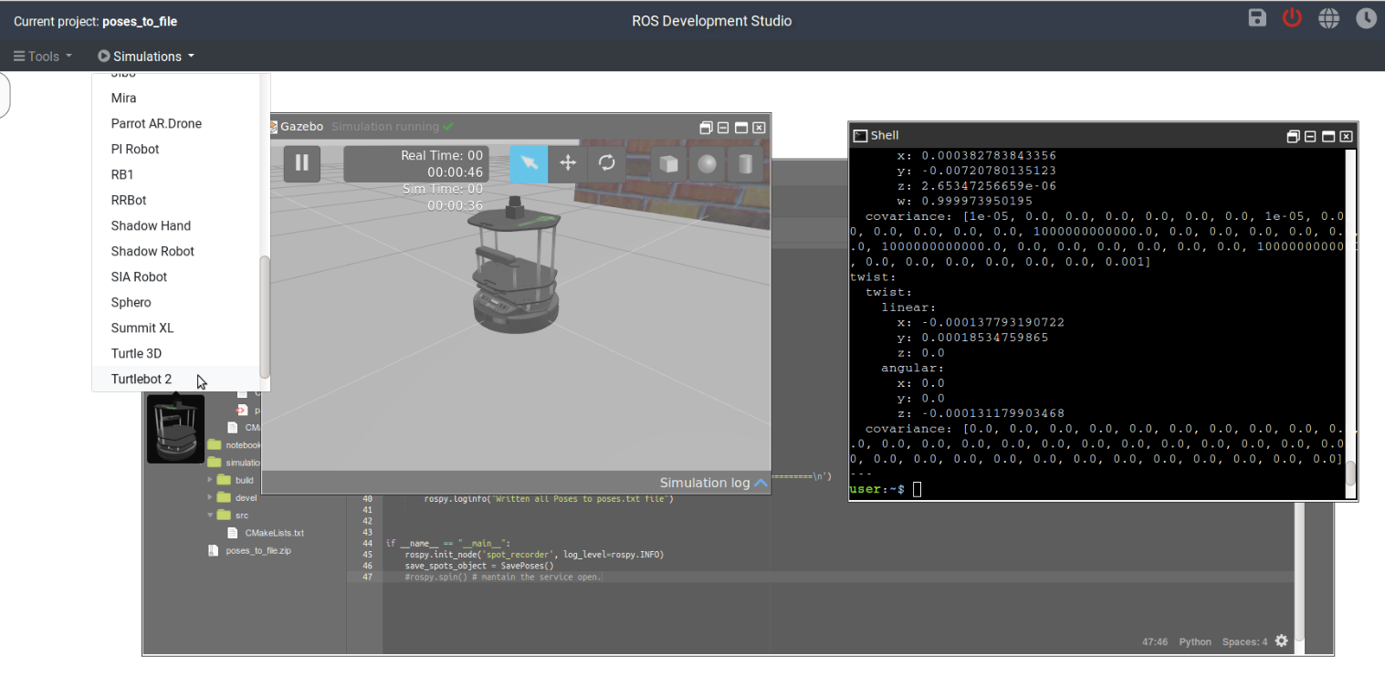
Before we run this script we need to start a simulation that will create a `/odom` topic. This topic will publish the odometry messages. Use the Simulations menu and select Turtlebot2 to start a simulation. Once the simulation is running you will see something like follows:
Now we can run the script with following command
$ rosrun poses_to_file poses_to_file.py
Let the script finish writing the poses to file. You will find a new file called poses.txt inside the src directory. This file will contain the poses as expected.
Thats about it. Enjoy learning ROS with Robot Ignite Academy.
In this video we are going to see how to convert a PointCloud into a laser scan. You can use later that laserscan as a lidar for robot navigation. This allows to do navigation with a very cheap sensor.
▸ Get the code of the video by clicking on this link: https://goo.gl/z3fNCs (You need an account on ROSDS. Once you click on the link, the whole code will appear on your ROSDS account ready to use. Watch the video for additional instructions)
Below are the step by step instructions for creating the project on ROSDS.
NOTE: if you are not using the ROSDS and you are using your local ROS installation, then you need to have installed the ROS package PointCloud To LaserScan (find the link below in the related links section).
Step 1
Head to Robot Development Studio and create a new project
Provide a suitable project name and some useful description (we are using the name “pointcloud to laser”)
Open the project (this will take few seconds)
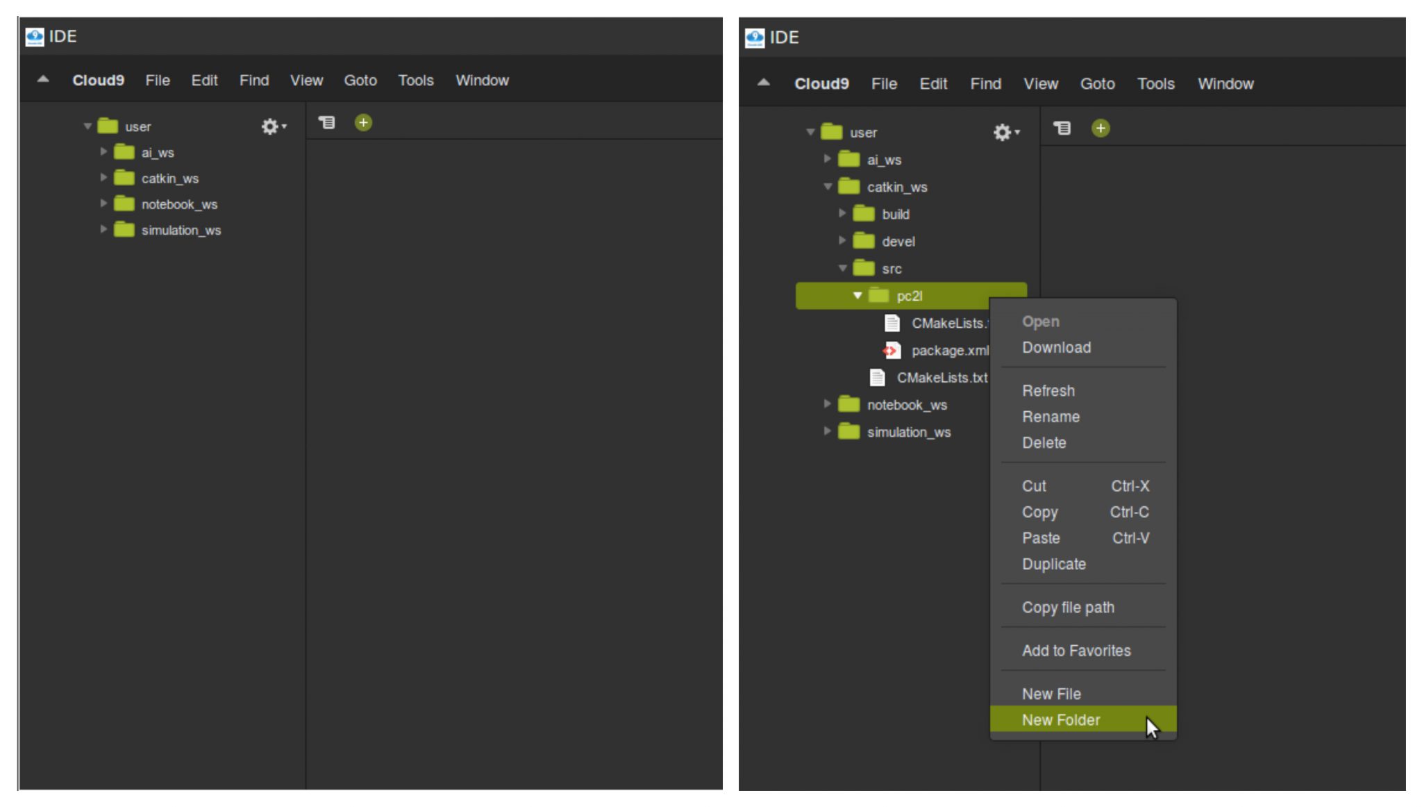
Once the project is loaded run the IDE from the tools menu. Also verify that the inital directory structure should look like following
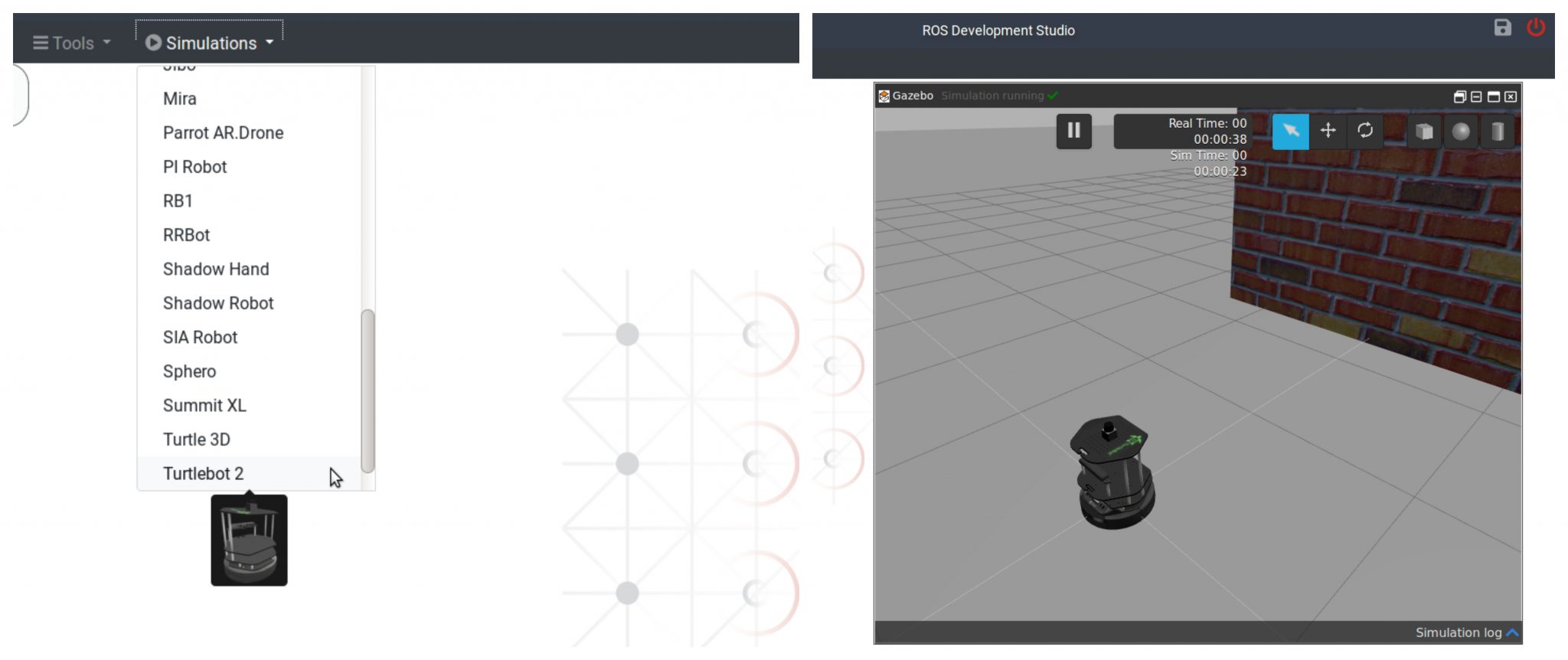
Simulate a turtlebot2 by choosing Turtlebot 2 option in the Simulation menu.
Next we will create a package pc2l (stands for PointCloud2Laser). Open a shell, browse to ~/catkin_ws/src directory and create a package with name pc2l
$ cd ~/catkin_ws/src
$ catkin_create_pkg pc2l
Further, we need to create a launch file that will create a node to do the conversion of pointcloud data to laser scan data (using pointcloud_to_laserscan library). We will create a launch directory then a launch file by name start.launch. We can use the IDE tool to achieve the same
Create a new file (inside the launch folder) with name start.launch and input the following contents (Note: The pointcloud_to_laserscan library needs to be installed in the system)
<launch>
    <node pkg="pointcloud_to_laserscan" type="pointcloud_to_laserscan_node" name="pointcloud_to_laserscan">
      <remap from="cloud_in" to="/camera/depth/points"/>
      <remap from="scan" to="/camera/scan" />
      <rosparam>
        target_frame: camera_link
        transform_tolerance: 0.01
        min_height: 0.0
        max_height: 1.0

        angle_min: -1.5708
        angle_max: 1.5708
        angle_increment: 0.0087
        scan_time: 0.3333
        range_min: 0.45
        range_max: 4.0
        use_inf: true

        #concurrency_level affects number of pc queued for processing and the number of threadsused
        # 0: Detect number of cores
        # 1: Single threaded
        # 2: inf : Parallelism level
        concurrency_level: 1
      </rosparam>
    </node>
</launch>
This **launch file** set’s up various parameters which are briefed below:
cloud_in : This argument contains the name of the topic that is publishing the pointcloud data. scan : This argument contains topic name (created by pointcloud_to_laserscan) that contains the converted scan data. target_frame : Tells the frame of reference for laser scan min and max height : Define the height range which will be taken into account while converting the pointcloud min and max angle : Define the range of angle over which laser scan data is composed about angle increment : The step increase in angle between conscuting scans scan time : The scan time is the interval between publishing two scans min and max range : This arguments defines the range of distance captured in the scans use inf : A point detected further than max range is encoded as inf point concurrency : This parameters controls how much cpu you want to allocate to the pointcloud to laser scan processing
Step 3
Now we can run the launch file, visualize the data (laser scan) and compare the pointcloud converted laser scan data with laser scan data provided by a laser scanner mounted on the robot.
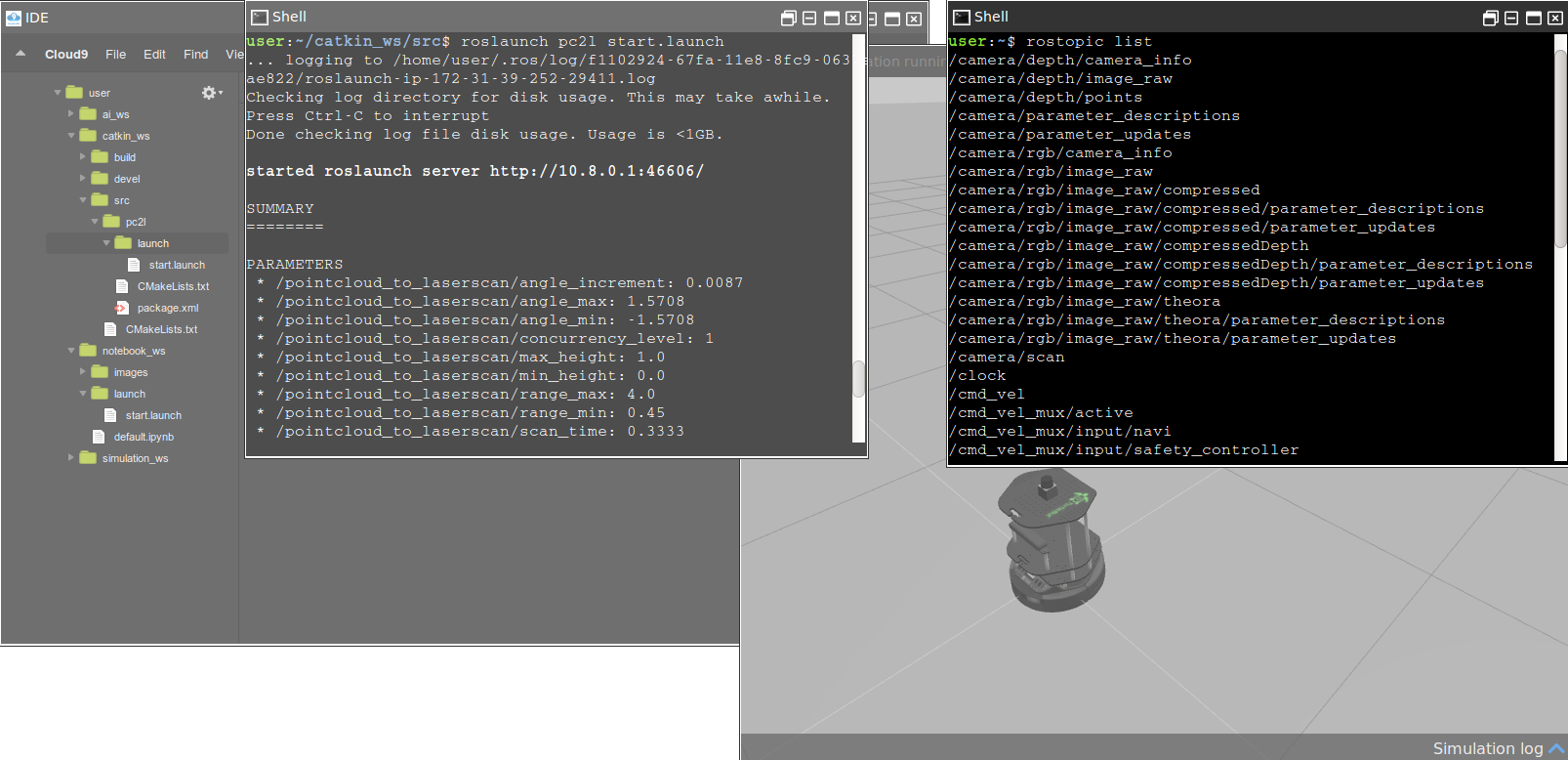
In the Shell type the following command to run the launch file
$ roslaunchg pc2l start.launch
This command will start a new topic with name /camera/scan. To verify start a new Shell and run the command
$ rostopic list
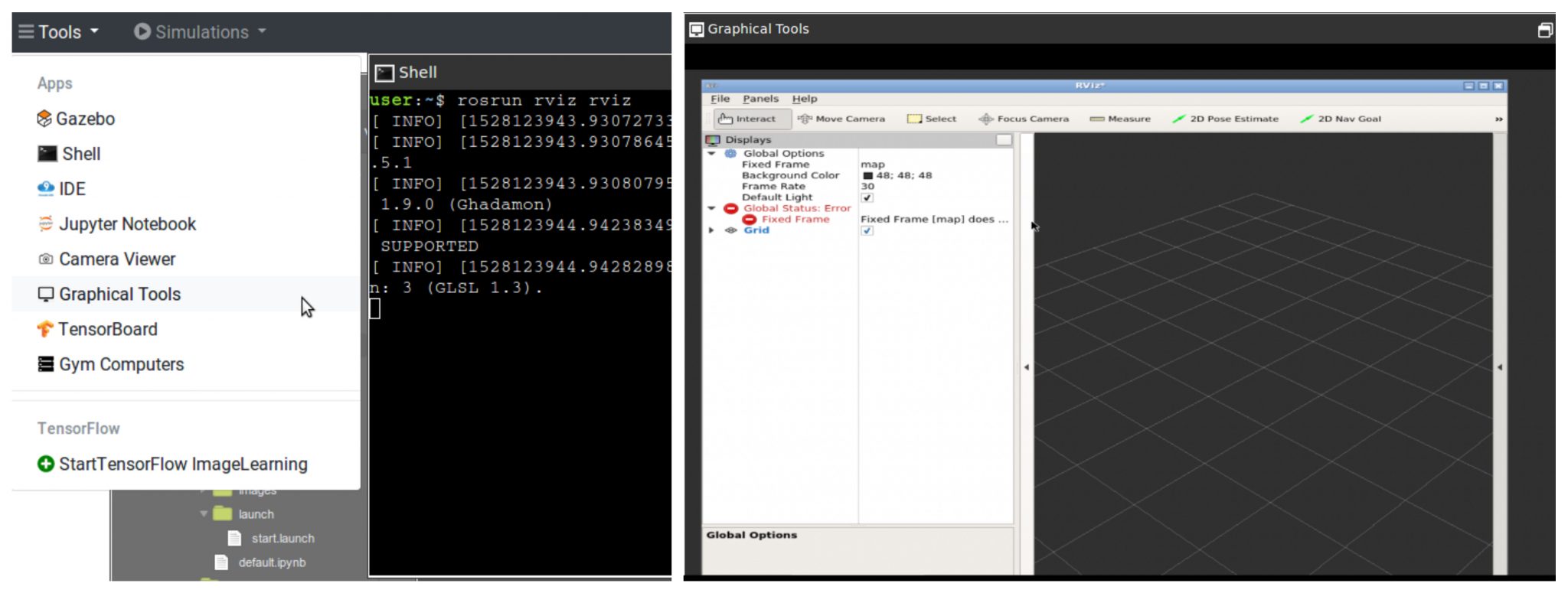
To visualize the data published over the /camera/scan topic we will run rviz In the shell, type the following command
$ rosrun rviz rviz
To see the rviz window we require a Graphical Tool
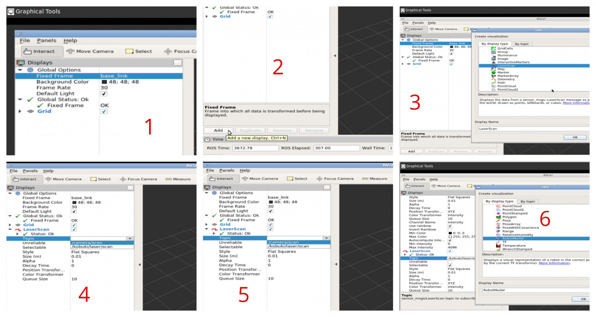
Once the rviz loads we will fix the errors by choosing appropriate value for Fixed Frame parameter. Then we will add following new displays
Laser display 1 : We will select the topic /camera/scan
Laser display 2 : We will select the topic /kobuki/laser/scan
Robot Model : We will add a robot model to visualize a turtlebot inside the rviz window
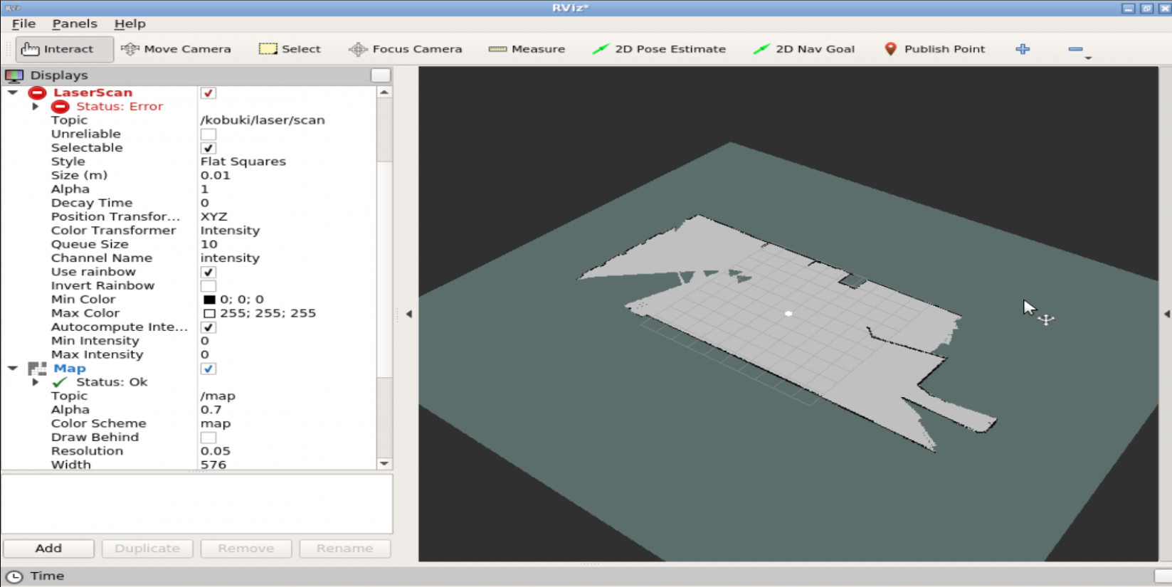
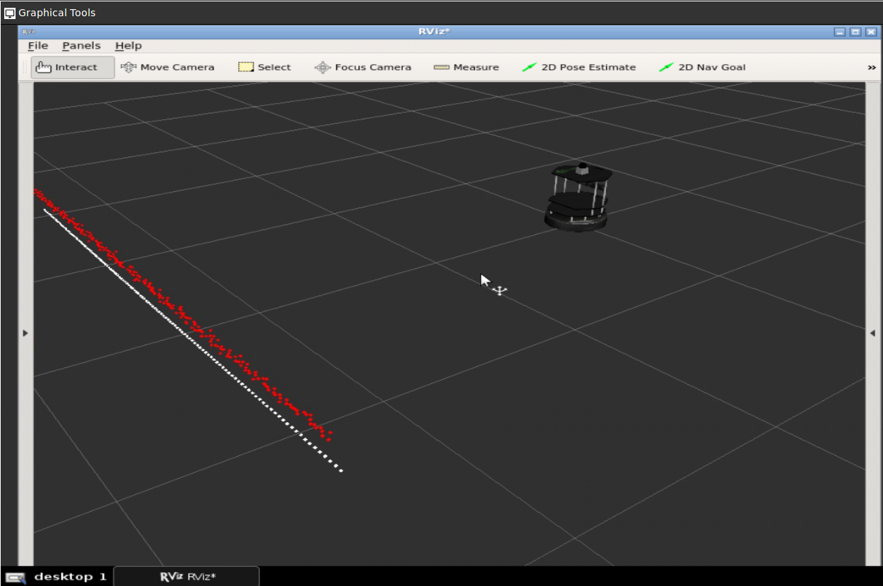
After we are done with all settings we will see the following
There are two laser scans one is from the /camera/scan (white colored) and the other is from /kobuki/laser/scan. We are done at this point.
// RELATED LINKS
▸ Point Cloud To LaserScan ROS package: http://wiki.ros.org/pointcloud_to_laserscan ▸ ROS Development Studio: https://goo.gl/tnjCD5 ▸ Robot Ignite Academy: https://goo.gl/8EhkWn ▸ ROS Navigation in 5 days online course: https://goo.gl/mkRYiR
In this ROS Mapping tutorial video we will see how to provide a previously created and saved map through topics, either using the command line or a ROS launch file.
The topic explained into this video is part of the ROS Navigation in 5 Days Course that you can find in the Robot Ignite Academy. You will find the links to both the academy and the Navigation Course right below.
Follow the steps to recreate the project as shown in the video
Go to Robot Ignite Academy. You will need to signup if you have not registered already.
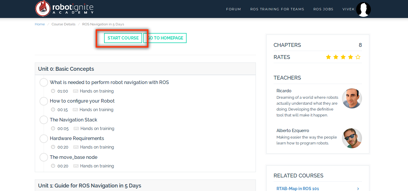
In the home page, choose the course ROS Navigation in 5 Days
Once the course page opens select start course option
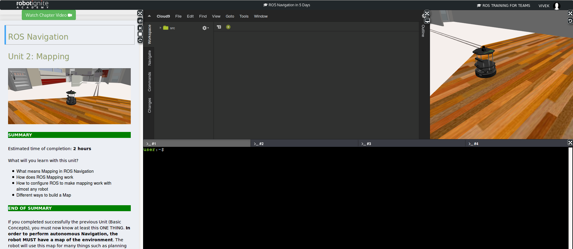
You should be greeted with the workspace like following (it will take a while to load the full page)
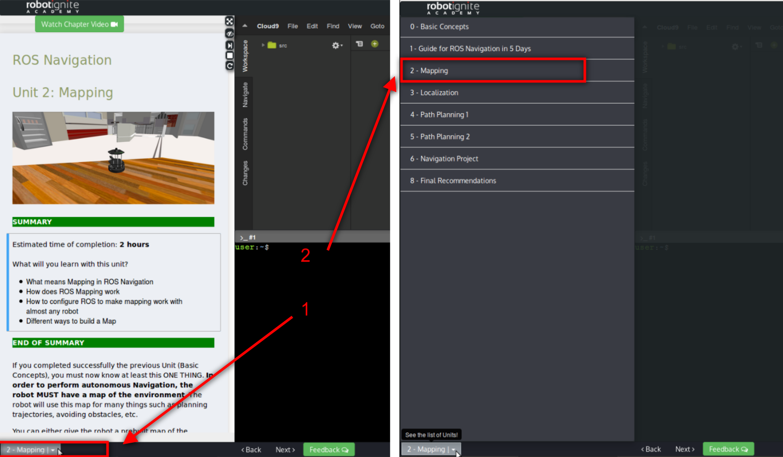
Open the Units menu from bottom left of the screen and select the Unit 2: Mapping
Start the gmapping package by executing the following command in a SHELL (there are four SHELL in the bottom of the screen)
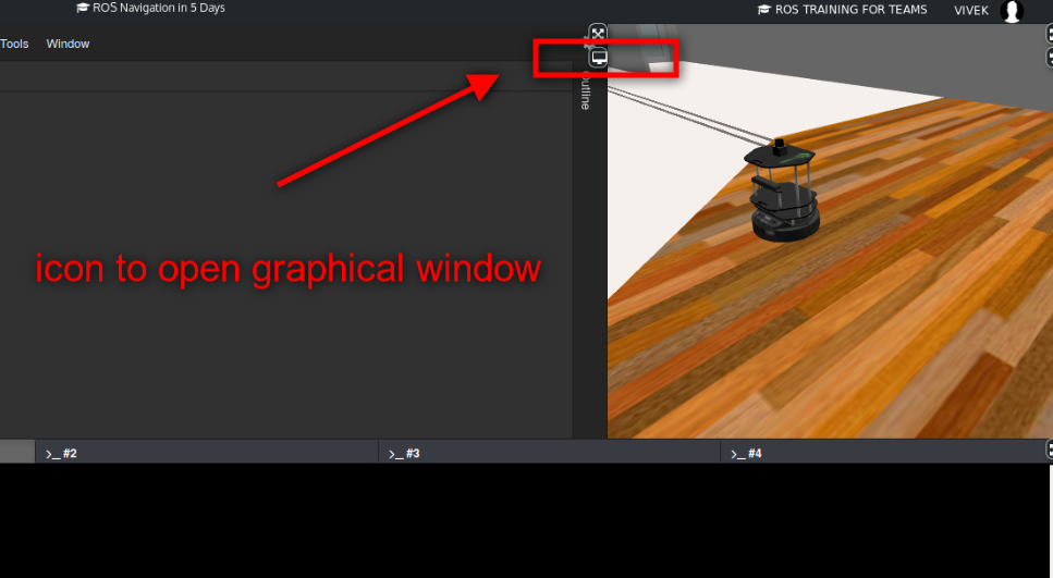
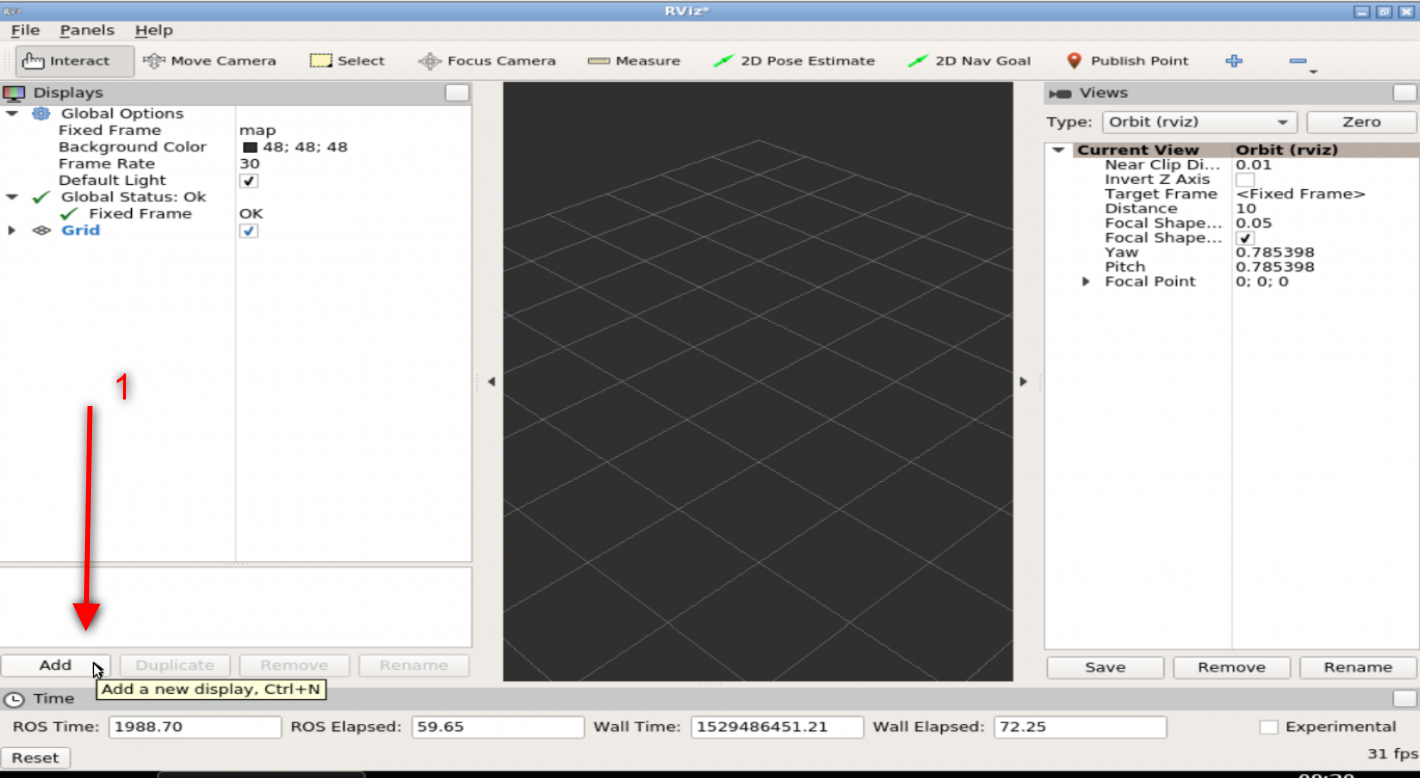
We will need a RVIZ windown to see the map visualization. Open a graphical interface window (see image)
Enter the following command in another SHELL to start the RVIZ visualization
$ rosrun rviz rviz
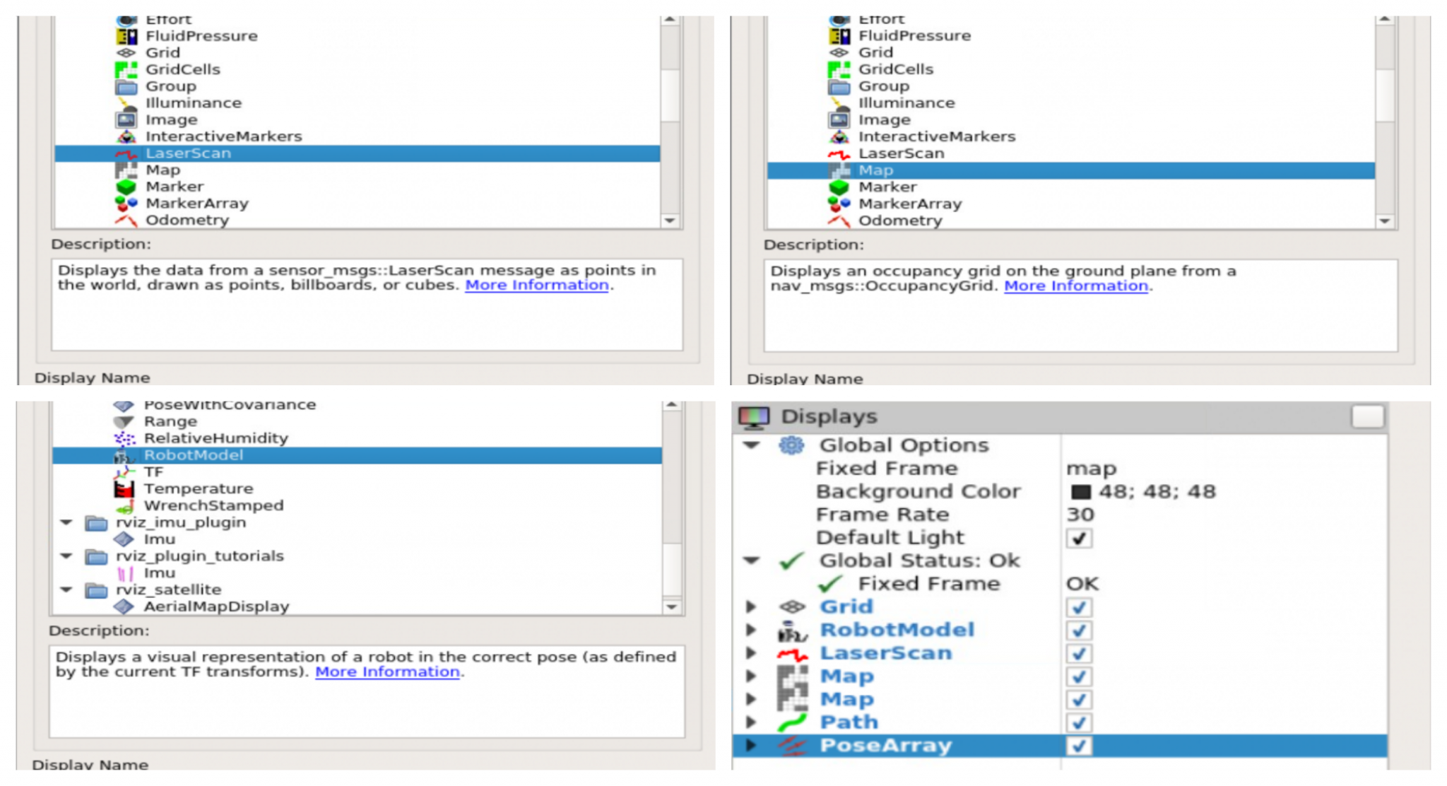
The above command will load the RVIZ in the graphical interface window as shown. We will add displays to the RVIZ window (as shown in image)
RobotModel
LaserScan
Map
Make the following settings
Map : set Topic to /map
Laser : set Topic to /kobuki/laser/scan
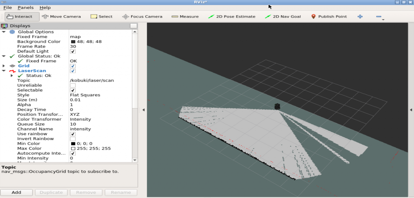
Once the above settings are made, you should start to see the visualization in the RVIZ window
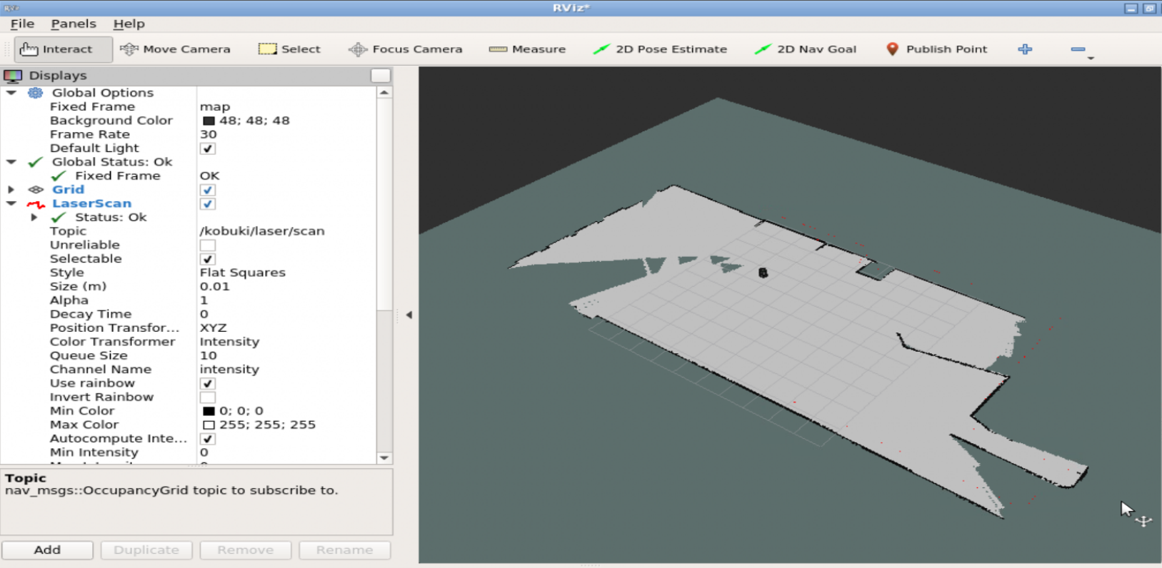
Now that mapping package is working, we will move the robot around to capture more data. To do so we will use the keyboard teleoperation, execute the following commands in a SHELL
Use the keys I(forward), J(left), L(right), M(backwards) to move the robot around. As you move the robot around the MAP in rviz should grow
To save the current map, execute the following command in a new SHELL
$ cd ~catkin_ws/src $ mkdir maps $ cd maps $ rosrun map_server map_saver -f my_map $ ls
You should see two new files created inside the ~/catkin_ws/src/maps directory
my_map.pgm
my_map.yaml
Now we can load this map to the map_server with the following command
$ rosrun map_server map_server my_map.yaml
The above command will start a map node with the map data in it. There is an alternate way to provide this map with the launch file. To provide the map using a launch file lets create a new package called provide_map. Execute the following commands in a SHELL
$ cd ~catkin_ws/src
$ catkin_create_pkg provide_map
$ cd provide_map
$ mkdir launch
$ mv ../maps . cd launch
$ touch provide_map.launch
The above commands create a new package by name provide_map and create a directory named launch inside the new package, it copies the maps directory (where we saved the maps) to inside the package and lastly creates a launch file provide_map.launch. Put the following content inside the launch file
From the URDF model, we’re going to define the first two links and visualize them in RViz. Up to the end of the video, we’ll have a basic model, a launch file to visualize it and a RViz configuration file for this specific project.
ROS Inside!
ROS Inside
Before anything else, if you want to use the logo above on your own robot or computer, feel free to download it and attach it to your robot. It is really free. Find it in the link below:
In order to follow this tutorial, we need to have ROS installed in our system, and ideally a ROS Workspace (it can be named simulation_ws). To make your life easier, we have already prepared a rosject with a simulation for that: https://app.theconstructsim.com/l/5a5b6f9f/.
You can download the rosject on your own computer if you want to work locally, but just by copying the rosject (clicking the link), you will have a setup already prepared for you.
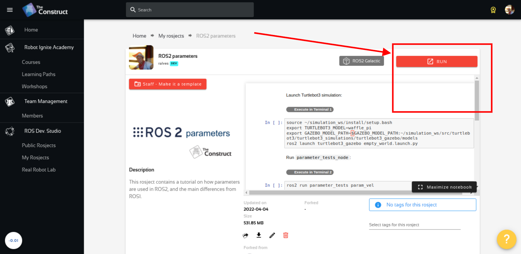
After the rosject has been successfully copied to your own area, you should see a Run button. Just click that button to launch the rosject (below you have a rosject example).
My Robotic Manipulator #1: Basic URDF & RViz – Run rosject (example of the RUN button)
After pressing the Run button, you should have the rosject loaded. Now, let’s head to the next section to get some real practice.
Compiling the workspace
As you may already know, instead of using a real robot, we are going to use a simulation. In order to see that simulated robot, we need to have our workspace compiled, and for that, we need a terminal.
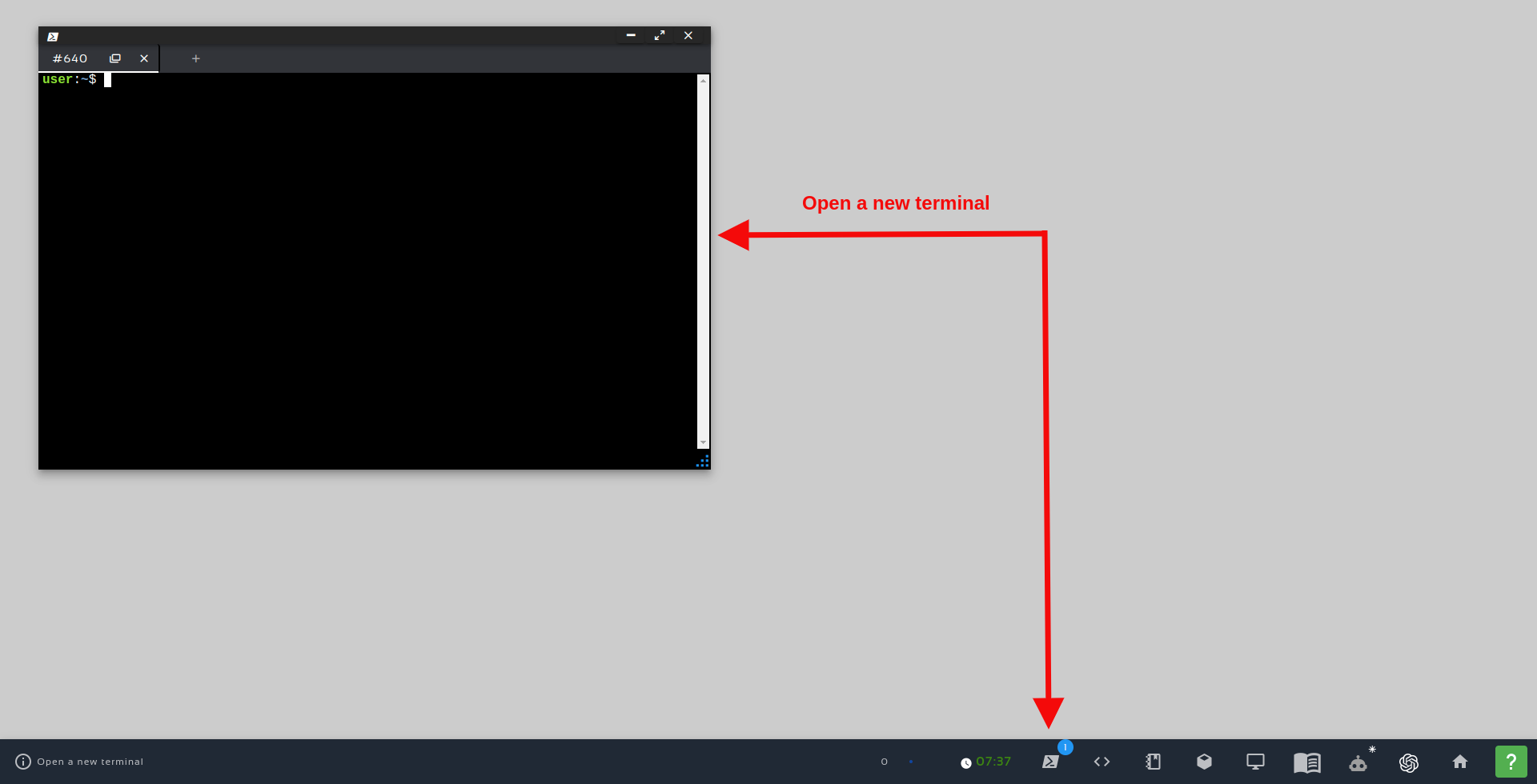
Let’s open a terminal by clicking the Open a new terminal button.
Open a new Terminal
Once inside the first terminal, let’s run the commands below, to compile the workspace
cd ~/simulation_ws/
catkin_make
source devel/setup.bash
How the mrm_description package was created
If you check the contents of the ~/simulation_ws/src folder using the Code Editor or the terminal, you will see that it already contains a package named mrm_description there (mrm stands for My Robotic Manipulator). In case you want to know the commands we used to create that package, the commands were the following (you don’t need to run these commands if you already have the rosject).
To create the package that has the urdf package as a dependency, the commands were the following after opening a terminal:
cd ~/simulation_ws/src
catkin_create_pkg mrm_description urdf
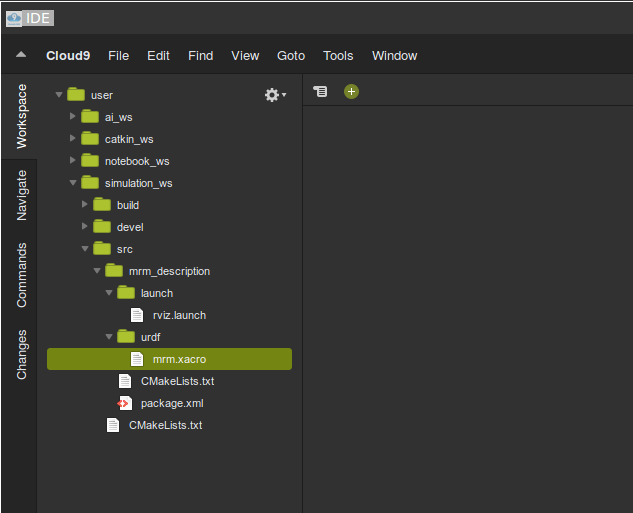
We then created a urdf folder inside the mrm_description package with:
cd mrm_description/
mkdir urdf
After the folder was created, we created a file named mrm.xacro using these commands:
cd urdf/
touch mrm.xacro
and we also created the rviz.launch file, used for launching RViz (Robot Visualization tool) with the following commands:
cd ~/simulation_ws/src/mrm_description/
mkdir launch

touch rviz.xacro
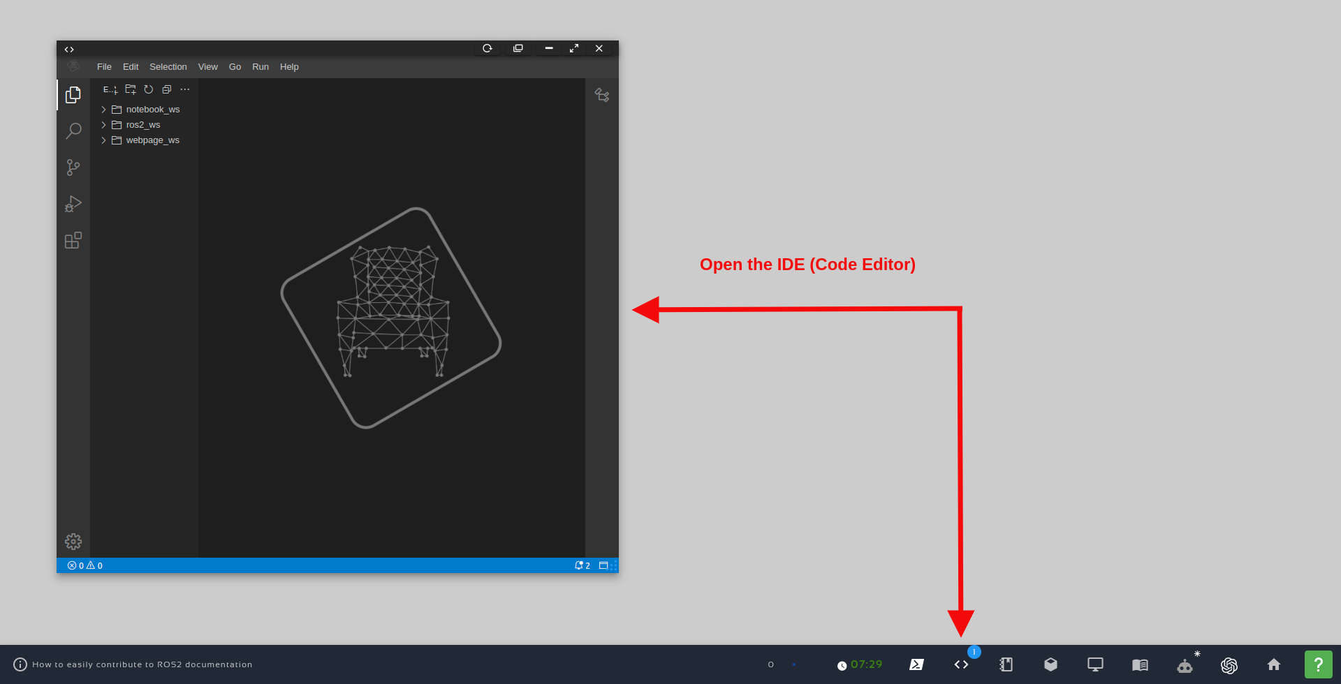
You can see the content of these files using the Code Editor, also known as IDE (Integraded Development Environment). In order to open the IDE, just click the Code Editor button, as we can see in the image below:
Open the IDE – Code Editor
Once the Code Editor is open, just navigate to simulation_ws/src/mrm_description/launch/rviz.launhc and simulation_ws/src/mrm_description/urdf/mrm.xacro to see the content of those files.
After opening the IDE, you can browse through folders by double-clicking them. In case you want to create a new folder, right click on the parent folder and choose the option New Folder and type in the name you want to give to the folder.
The mrm.xacro file (My Robot Manipulator xacro file)
If we check the content of the mrm.xacro file, be it using the Code Editor or using the terminal (cat ~/simulation_ws/src/mrm_description/urdf/mrm.xacro), we will find the following:
Then we define a link named base_link , with his visual being a box of width, depth, and height of 1 meter. The origin of the base_link is at the center of the simulated world, at position 0 0 0:
Then we create a joint to connect the base_link we just created, with a link named link_01 that we are about to create. The joint was defined with this code:
In summary, this xacro file is a description of our robot in xml language. The robot is composed of various links and joints. In the above xacro we have two links base_link and link1. The base_link is fixed to the ground. It is connected to the link1 with a revolute joint. The joint allows the link1 to rotate about z-axis. We are defining the visual properties in this file.
The geometry property controls the appearance and origin property controls the positioning of the elements.
The joint element has an axis property which defines the degree of freedom of the links connected with joint. In addition to the axis property, the joint element has limit property to control the range of motion, parent and child property to control the relative motion (the child link moves with respect to the parent link).
Now that we have our robot defined, we need a way of launhcing it. For that, we have the rviz.launch file mentioned earlier. Let understand it:
The rviz.launch file
The content of the rviz.launch file that we created in the previous sections can be seen either using the Code Editor or through the terminal using this command:
In the fist line we start the definition of the launch file using the <launch> tag.
In the second line, we load a ROS parameter called robot_description using the content of of the urdf/mrm.xacro file that is found on the mrm_description package. It is basically the xacro file explained in the previous section.
In order to “put the robot pieces together“, we use the robot_state_publisher:
We also launch RViz in that launch file, and tell it to load the launch/config.rviz file that is also inside our package. Having that config.rviz file, we don’t have to reconfigure the RViz displays each time we open RViz.
Finally, we load the Joint State Publisher that allows us to move/rotate the links of our robot using a Graphical Tool:
To summarize, this launch file helps in the task of launching different nodes together. The rviz.launch file above creates three nodes. The first node is for publishing the robot state, the second node starts RViz and the last node starts a GUI tool that helps in manipulating the joint angle of the robot. The first line (param) helps in locating and loading the xacro file that contains the robot description.
Compiling the workspace
Now that we have everything in place, we need to compile our workspace. For that, we use the following commands:
cd ~/simulation_ws/
catkin_make
If everything went well, you should have an output similar to the following:
...
-- catkin 0.8.10
-- BUILD_SHARED_LIBS is on
-- BUILD_SHARED_LIBS is on
-- ~~~~~~~~~~~~~~~~~~~~~~~~~~~~~~~~~~~~~~~~~~~~~~~~~
-- ~~  traversing 1 packages in topological order:
-- ~~  - mrm_description
-- ~~~~~~~~~~~~~~~~~~~~~~~~~~~~~~~~~~~~~~~~~~~~~~~~~
-- +++ processing catkin package: 'mrm_description'
-- ==> add_subdirectory(mrm_description)
-- Configuring done
-- Generating done
-- Build files have been written to: /home/user/simulation_ws/build
####
#### Running command: "make -j8 -l8" in "/home/user/simulation_ws/build"
####
Lauching RViz to see our robot model
In the previous sections we already learned how to open a terminal.
Now, in order to launch RViz, let’s run the following commands in the first terminal:
After running this launch file, you should have seen RViz and the Joint State Publisher. If RViz does not open automatically, just click the Graphical Tools button on the bottom bar of The Construct Desktop. If you don’t know which button is, just hover your mouse over the buttons to know which one opens the Graphical Tools.
After having the Graphical Tools open, feel free to move the joining using the Joint State Publisher. It is going to be difficult to see the joint moving because it has the same red color as the base link, but if you look at RViz closely, you will see it moving.
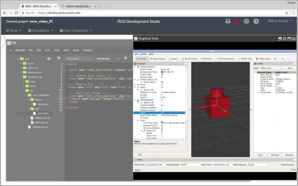
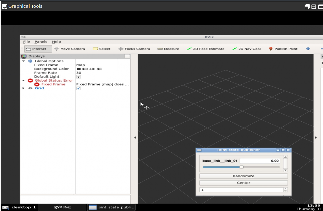
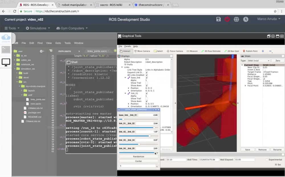
The GUI tool is like a remote desktop, when it starts you can see there are two tabs at the bottom. One is the RViz tool, and the other is the joint_state_publisher GUI as shown below:
In the RViz window, we should have everything in place. We shouldn’t have the red errors like in the image above, because in the rosject we already provided the config.rviz in the launch file, if you remember well.
What we did for creating that config.rviz file was the following, in RViz:
Changed Fixed Frame to base_link
Added an Axis element
Added a RobotModel element
The images below show the operations described above:
Congratulations. Now you know how to create a basic robot with two links and a joint using Xacro files.
We hope this post was really helpful to you. If you want a live version of this post with more details, please check the video in the next section. Although the video was recorded in a previous version of The Construct platform, it still adds a lot of value:
Youtube video
So this is the post for today. Remember that we have the live version of this post on YouTube. If you liked the content, please consider subscribing to our youtube channel. We are publishing new content ~every day.
Keep pushing your ROS Learning.
Related Courses & Training
If you want to learn more about ROS and ROS2, we recommend the following courses:
In this video we will see how to launch a complex industrial environment with several robots in it, including ROS industrial robots and service robots.
The simulation contains a UR5 industrial robot and a couple of mobile bases. Also, many types of sensors include, including lasers cameras, and even a conveyor belt simulation.
This amazing simulation was created by the OSRF for their ARIAC competition 2017 using Gazebo simulator
[irp posts=”8409″ name=”RDP 006: Using ROS for Industrial Projects With Carlos Rosales”]
Step 1. Create a project in ROS Development Studio(ROSDS)
ROSDS helps you follow our tutorial in a fast pace without dealing without setting up an environment locally. If you haven’t had an account yet, you can create a free account here. You can get the shared project through this link .
Step 2. Run the simulation
We prebuilt the package for this project. You can run the simulation with the following command
![[ROS Q&A] 119 – ROS Mapping Tutorial. How To Provide a Map](https://www.theconstruct.ai/wp-content/uploads/2018/05/ROS-Mapping-Tutorial.-How-To-Provide-a-Map.png)