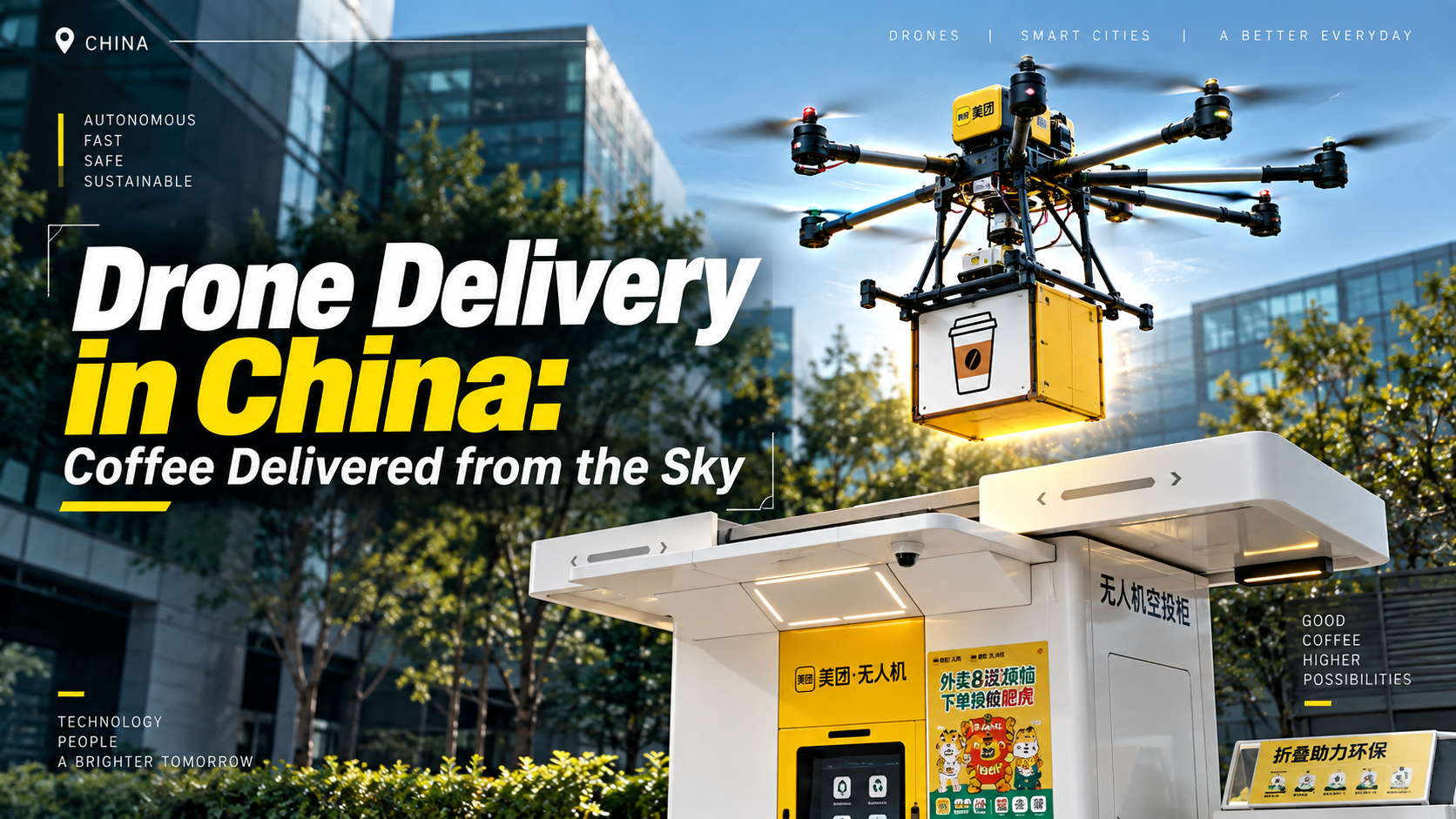
Ordering something from the middle of the street and having it delivered by a drone sounds like something from the future.
But in China, it is already happening.
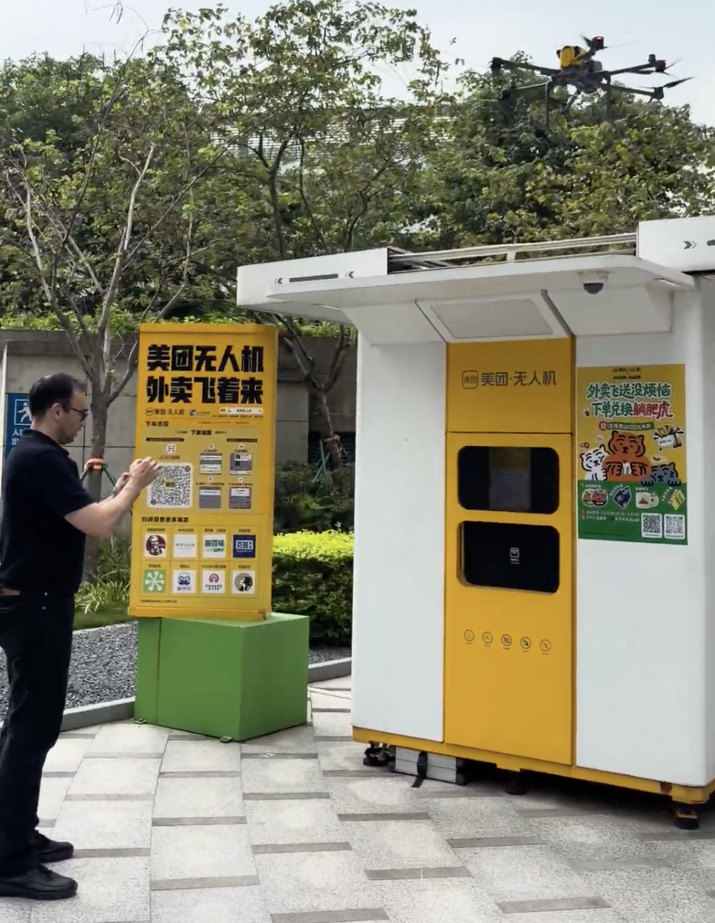
I had heard about drone delivery systems before, so when I visited Shenzhen Technology Park, I decided to try one for myself. I found a drone delivery station right on the street, with people regularly placing orders and collecting their packages. It wasn’t a demonstration. The system was simply running as part of everyday life.
So I decided to order a coffee and see what would happen!
How Drone Delivery Actually Works
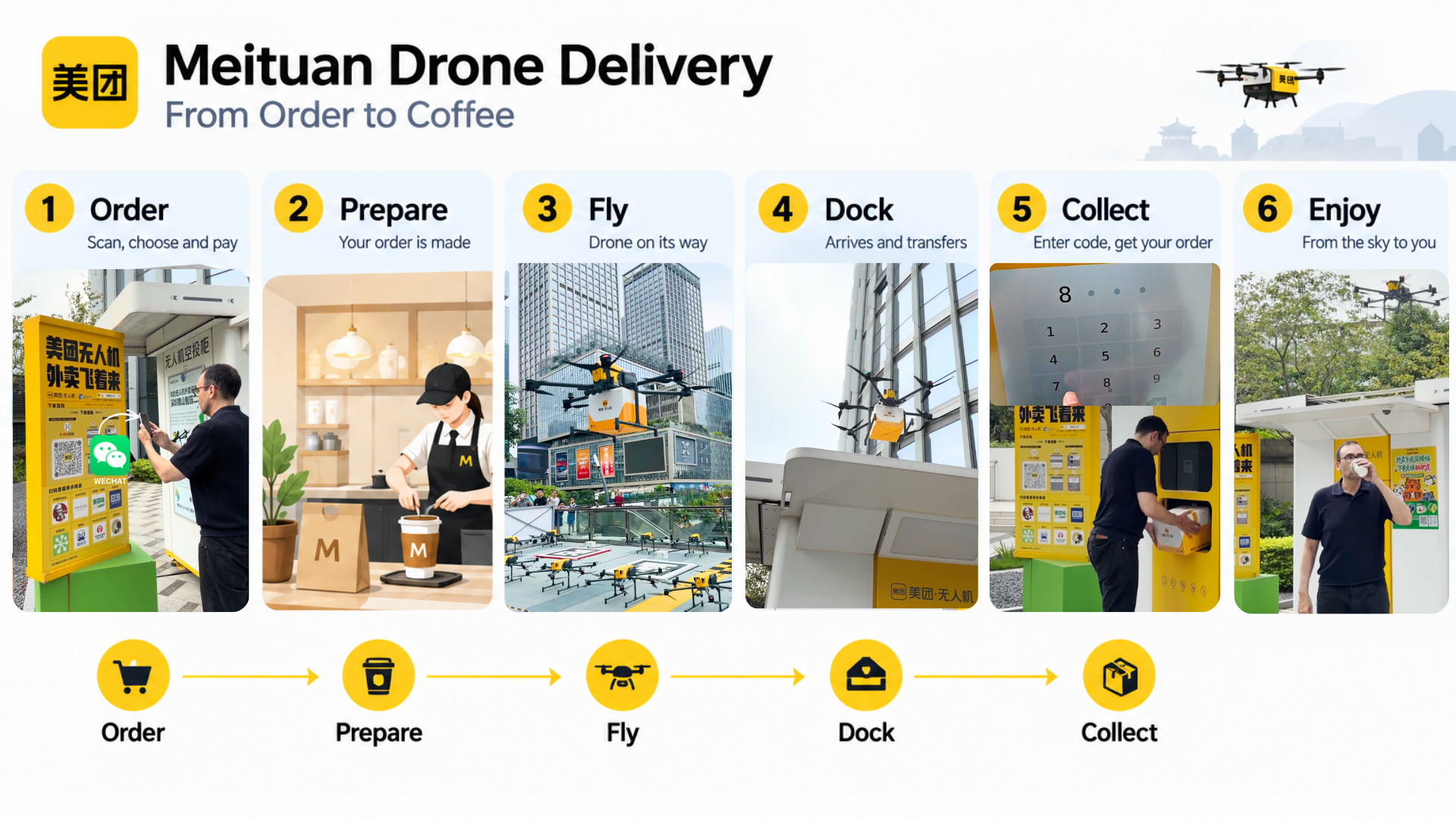
The process starts at the delivery station. I scanned the QR code with WeChat, which opened the ordering interface and let me choose what I wanted. I placed my order, paid through the app, and waited for it to be prepared.
While I was waiting, the app kept updating the status of my order. Somewhere nearby, the coffee was being prepared and packaged before being sent to the station.
Once the order was ready, the app showed that the drone was on its way. I could follow its location on my phone as it approached the station, although I still couldn’t see it in the sky.
Then, a few moments later, I saw it.
The drone arrived directly above the station, descended vertically, and docked. The package was transferred from the drone into the delivery station, where it was stored until I came to collect it.
The app then gave me a collection code. I entered it on the station’s screen, the compartment opened, and there was my coffee.
A few minutes earlier, it had been traveling through the air on an autonomous drone. Now, I was drinking it.
The whole experience was surprisingly simple. From the customer’s perspective, it was essentially:
Order → Prepare → Fly → Dock → Collect
A Few Things I Noticed
There were a few things that caught my attention while watching the system operate.
1. There seemed to be a highway in the air.
The drones were consistently following very similar trajectories, suggesting that their movements are carefully coordinated rather than completely independent. It reminded me of how robot fleets are managed in warehouses, where coordinating many robots is just as important as making each robot autonomous.
2. Making this work in the real world is a completely different challenge from making a demo.
The process looks simple, but having drones operate reliably with real customers, real packages, and real deliveries at scale takes an enormous amount of engineering. Meituan has clearly done a remarkable job turning the technology into a real service. Building a video demo is one thing; running a system like this in the real world is another. Kudos to the team.
3. An important lesson in how the system was deployed.
You still need to go to a delivery station to collect your package, so this isn’t yet a system that can deliver wherever you are. But it works, and it works at scale. Instead of waiting to build the perfect system, Meituan solved one part of the problem, deployed it, gathered real-world data, and can now use that experience to tackle the next stage. In robotics, that step-by-step approach is often much more realistic than trying to solve everything at once.
Seeing a system like this operating in the real world is a good reminder of how quickly robotics is moving beyond the lab and into everyday life.
And as robotics becomes more accessible, you don’t need an engineering degree to start being part of it.
The Robotics Developer Masterclass helps you start from zero, build real robotics projects, and develop the practical skills you need to start working toward a career in robotics — in as little as 6 months.
The future of robotics is already being built. Now it’s your turn.
The best way to learn robotics is by building a real robot yourself. You don’t just learn the theory—you see how different components work together in a real system.
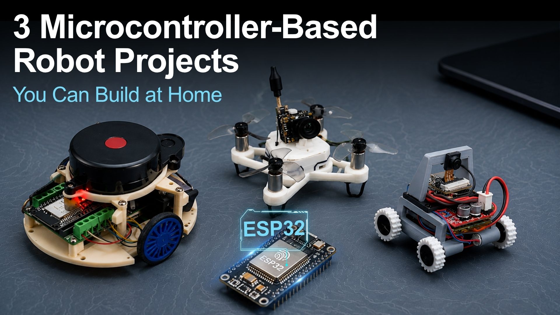
If you’re looking for a hands-on robotics project you can build at home, We’d like to show you three very different robots. One is an autonomous mobile robot, another one flies, and the third is so compact that it can be used as a mini spy robot.
Although they serve different purposes, they all have one thing in common: they’re all built around the ESP32 microcontroller. That means they’re affordable, powerful, and capable of running micro-ROS, making them excellent platforms for learning modern robotics.
Let’s take a closer look at each one.
Why microcontroller + ROS 2 matters
Before we jump into the projects, there is one important idea to understand.
A robot is usually split into two parts:
The microcontroller is the muscle
It reads sensors and controls motors in real time.
ROS 2 is the brain
It handles mapping, planning, decision-making, and other computationally intensive tasks.
When you connect the two using micro-ROS, you get the best of both worlds. The robot stays responsive while a computer running ROS 2 performs the heavy computation.
This is exactly how many real-world robotics systems are built, and understanding this architecture is one of the most valuable skills you can develop as a robotics engineer.
If you’re just getting started with robotics, this is probably the best project to begin with.
Credit: Maker`s Pet (YouTube)
This robot uses a classic two-wheel differential drive design with a LiDAR mounted on top. An ESP32-based controller handles the motors, while a desktop computer running ROS 2 takes care of mapping and autonomous navigation.
Using micro-ROS, the robot streams sensor data to the computer, allowing you to:
Build maps of your environment
Run autonomous navigation
Detect and avoid obstacles
Experiment with SLAM and ROS 2 Navigation
Besides being a fun robot to build, this project teaches one of the most important concepts in robotics: distributing computation between an embedded controller and an external computer.
If you want to work in robotics professionally, this is an architecture you’ll encounter again and again.
This is the hardest project on the list, but it’s also the coolest because it actually flies.
Everything fits into a tiny frame:
An ESP32-based flight controller
Compact motors
A lightweight battery
A small quadcopter frame
You can control the drone in two different ways:
Through the ESP-Drone mobile app
Using a radio controller via ESP-NOW for longer range and better precision
This project doesn’t currently use micro-ROS, which actually makes it a great opportunity to extend it yourself. Adding micro-ROS support would be an excellent exercise if you’re looking to deepen your understanding of distributed robotics systems.
If you want a project that will really challenge your skills, this is the one to build.
The third project is much smaller, but no less interesting.
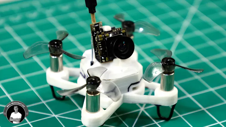
Think of it as a miniature version of the first robot. Instead of a LiDAR, it uses a small camera connected directly to an ESP32 board.
Credit: The Wrench (YouTube)
Because of its tiny size, it almost feels like building your own mini spy robot.
Using the companion mobile app, you can:
Drive the robot remotely
View live video from the onboard camera
Like the quadcopter, this project doesn’t use micro-ROS out of the box. Replacing its control system with a micro-ROS implementation would make an excellent learning exercise and help you practice integrating embedded hardware with the ROS 2 ecosystem.
What You’ll Learn
Although these three robots look completely different, they’re all built around the same core ideas.
By building them, you’ll gain hands-on experience with:
Motor control
Sensor integration
Wireless communication
Embedded programming
Computer vision
Autonomous navigation
ROS 2 and micro-ROS communication
System integration
These aren’t just hobby skills—they’re the same foundations used in professional robotics systems.
Which Project Should You Build?
Not sure where to start?
Here’s a simple guide:
Interested in autonomous robots? Start with the two-wheel robot.
Want the biggest challenge? Build the mini quadcopter.
Interested in cameras and embedded systems? Try the tiny four-wheel robot.
Whichever project you choose, you’ll build practical robotics skills while creating something genuinely fun.
Final Thoughts
These three projects may look very different, but they’re all built on the same foundation: an ESP32 microcontroller and the core principles behind modern robotics.
Whether you’re building a mobile robot, a drone, or a tiny camera rover, you’ll gain hands-on experience with the technologies that power real robotic systems.
So pick the project that excites you most and start building.
These projects are a great starting point, but professional robotics goes far beyond assembling hardware. You’ll also need to understand ROS 2, robot software architecture, perception, navigation, and system integration.
That’s exactly what The Construct’s Robotics Developer Masterclass is designed to teach. Starting from zero, you’ll build the practical robotics skills used in industry through hands-on projects—no engineering degree required, just the passion to become a robotics developer.
Finally, Intrinsic (a spin-off of Google-X) has revealed the product they have been working with the help of the Open Source Robotics Corporation team (among others): Flowstate!
What is Flowstate?
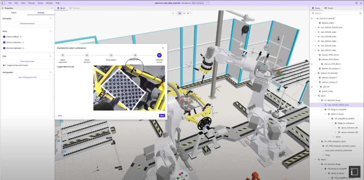
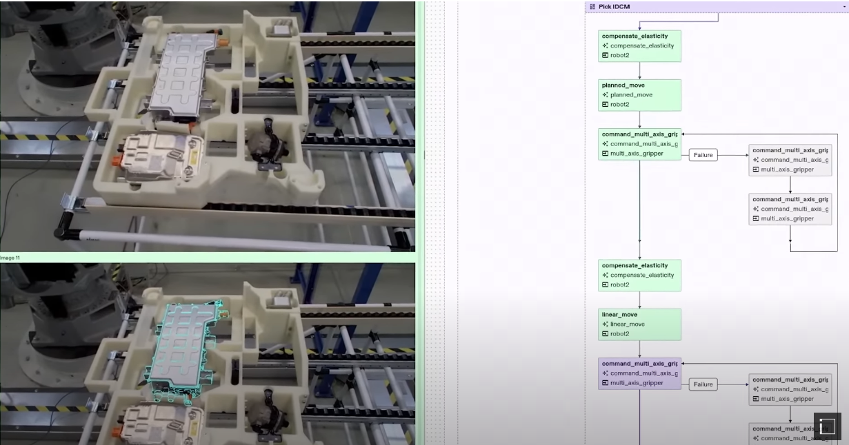
Introducing Intrinsic Flowstate | Intrinsic (image copyright by Intrinsic)
Flowstate is a web-based software designed to simplify the creation of software applications for industrial robots. The application provides a user-friendly desktop environment where blocks can be combined to define the desired behavior of an industrial robot for specific tasks.
Good points
Flowstate offers a range of features, including simulation testing, debugging tools, and seamless deployment to real robots.
It is based on ROS, so we should be able to use our favorite framework and all the existing software to program on it, including Gazebo simulations
It has a behavior tree based system to graphically control the flow of the program, which simplifies the way to create programs by just moving blocks around. But it is also possible to switch to expert mode to manually touch the code
It has a library of already existing robot models and hardware ready to be added, but you can also add your own
Additionally, the application provides pre-built AI skills that can be utilized as modules to achieve complex AI results without the need for manual coding
One limitiation (but I actually consider a good point) is that the tool is thought for industrial robots not for service robots in general. This is good because it provides a focus for the product, specially for this initial release
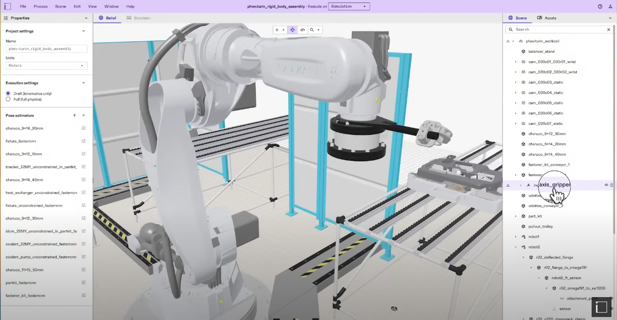
Flowstate | Intrinsic (image copyright by Intrinsic)
Based on the official post and the keynote released on Monday, May 15, 2023 (available here: https://intrinsic.ai/blog/posts/introducing-intrinsic-flowstate/), this is the information we have gathered so far. However, we currently lack a comprehensive understanding of how the software works, its complete feature set, and any potential limitations. To gain more insights, we must wait until July of this year, hoping that I will be among the lucky participants selected for the private beta (open call to the beta still available here: https://intrinsic.ai/beta/).
Unclear points
Even if I find interesting the proposal of Intrinsic, I have identified three potential concerns regarding it:
Interoperability across different hardware and software platforms poses a challenge. The recruitment of the full OSRC team by Intrinsic appears to address this issue, given that ROS is currently the closest system in the market to achieve such interoperability. However, widespread adoption of ROS by industrial robot manufacturers is still limited, with only a few companies embracing it.
Ensuring hardware interoperability necessitates the adoption of a common framework by robot manufacturers, which is currently a distant reality. What we, ROS developers, aim right now is to be able to have somebody build the ROS drivers for the robotic arm we want to use (like for example the manufacturers of the robot, or the team of ROS Industrial). However, manufacturers generally hesitate to develop ROS drivers due to potential business limitations and their aims for customer lock-in. Unless a platform dedicates substantial resources to developing and maintaining drivers for supported robots, the challenge of hardware interoperability cannot be solved by a platform alone (actually, that is one of the goals that ROS-Industrial is trying to achieve).
Google possesses the potential to unite hardware companies towards this goal, as Wendy Tan White, the CEO of Intrinsic mentioned, “This is an ecosystem effort” However, it is crucial for the industrial community to perceive tangible benefits and value in supporting this initiative beyond merely assisting others in building their businesses. The specific benefits that the ecosystem stands to gain by supporting this initiative remain unclear.
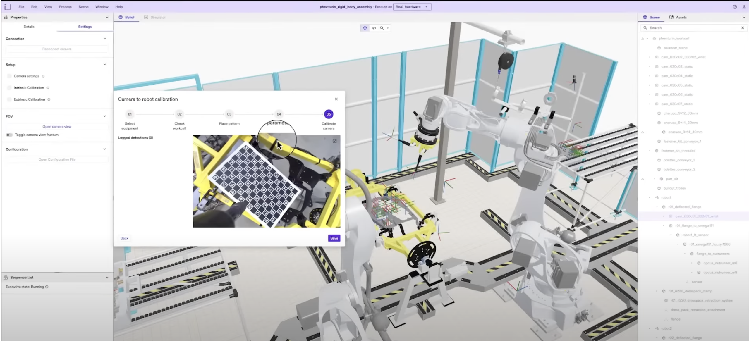
Flowstate | Intrinsic (image copyright by Intrinsic)
The availability of pre-made AI skills for robots is a complex task. Consider the widely used skills in ROS, such as navigation or arm path planning, exemplified by Nav2 and MoveIt, which offer excellent functionality. However, integrating these skills into new robots is not as simple as plug-and-play. In fact, dedicated courses exist to teach users how to effectively utilize the different components of navigation within a robot. This highlights the challenges associated with implementing such skills for robots in general. Thus, it is reasonable to anticipate similar difficulties in developing pre-made skills within Flowstate
A final point that I don’t see clear (because it was not addressed in the presentation) is how the company is going to do business with Flowstate. This is a very important point for every robotics developer because we don’t want to be locked into proprietary systems. We understand that companies must have a business, but we want to understand clearly what the business is so we can decide if that is convenient or not for us, both in the short and the long run. For instance, Robomaker from Amazon did not gain much traction because forced the developers to pay for the cloud while running Robomaker, when they could do the same thing (with less fancy stuff) in their own local computers for free
Conclusion
Overall, while Flowstate shows promising, further information and hands-on experience are required to assess its effectiveness and address potential challenges.
I have applied to the restricted beta. I hope to be selected so I can have a first hand experience and report about it.
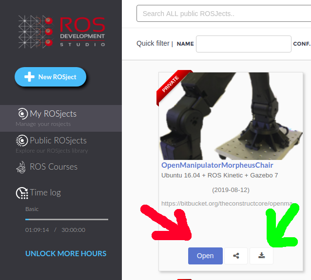
You can open it by clicking on the Open button or you can download it by clicking on the download button, the ones pointed below by the red and green arrows respectively.
The ROSJect mentioned here basically contains the following git repositories on it:
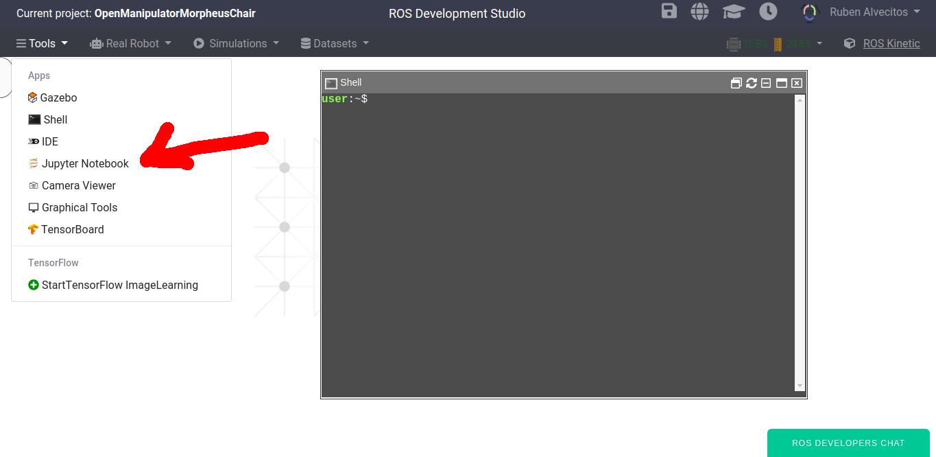
When you open a ROSject, by default you have the Jupyter Notebook automatically open, but if that doesn’t happen, you can manually open it by clicking on Tools -> Jupyter Notebook as shown in the image below:
Now on the Jupyter Notebook window let’s click openmanipulator_morpheus_chair_notebooks, then click on Notes_Commands.ipynb to open it. That notebook contains the instructions we are going to follow in this post.
Start Demo Pick and place Everything:
In order to start the demo, let’s first run the Service Server that will be used to move the arm:
Following up our previous post about how to control a Robot Arm with ROS, today we are going to learn how to set up a MoveIt package for controlling the arm.
In short, in this post we will learn the following:
How to create a basic MoveIt package for your own robot
Test that package moving and planning with moveit.
Special Thanks to Clarkson University and specially James Carrol and its team for lending us the physical Open Manipulator robot.
Getting the code
We are going to create the MoveIt package which uses some URDF files. In order to get the URDF files, please get the following ROSject: http://www.rosject.io/l/b368f5c/
You can open it by clicking on the Open button or you can download it by clicking on the download button, the ones pointed below by the red and green arrows respectively.
The ROSJect mentioned here basically contains the following git repositories on it:
When you open a ROSject, by default you have the Jupyter Notebook automatically open, but if that doesn’t happen, you can manually open it by clicking on Tools -> Jupyter Notebook as shown in the image below:
Now on the Jupyter Notebook window let’s click openmanipulator_morpheus_chair_notebooks, then click on Ep3_MoveIt!_First_Steps.ipynb to open it. That notebook contains the instructions we are going to follow in this post.
The URDF file we are going to use
If you opened or downloaded the ROSject you will see that we have a package called open_manipulator_support_description with the .xacro file called open_manipulator_support.urdf.xacro. If you opened the ROSject on n ROSDS (ROS Development Studio), the full path to that file is: ~/simulation_ws/src/open_manipulator_tc/open_manipulator_support_description/urdf
The content of open_manipulator_support.urdf.xacro is:
Now that we know which urdf/xacro file we are going to use, let’s create a MoveIt package. On the ROSject that we are using that package is already created for you and it’s available on the path /home/user/catkin_ws/src/openmanipulator_ep2_movit_config, but we are going to show how we created it.
In order to open the MoveIt Assistant, the program used to create our first MoveIt Package, we used the following commands:
cd ~/catkin_ws/src
roslaunch moveit_setup_assistant setup_assistant.launch
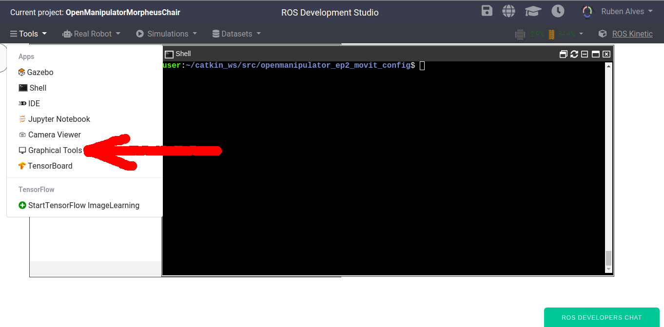
MoveIt Assistant is a graphical application, so, after running the command aforementioned, on ROSDS you have to open the Graphical Tools by clicking Tools -> Graphical Tools as shown below:
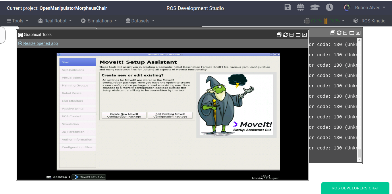
After clicking on that button we should see MoveIt Setup Assistant as in the image below:
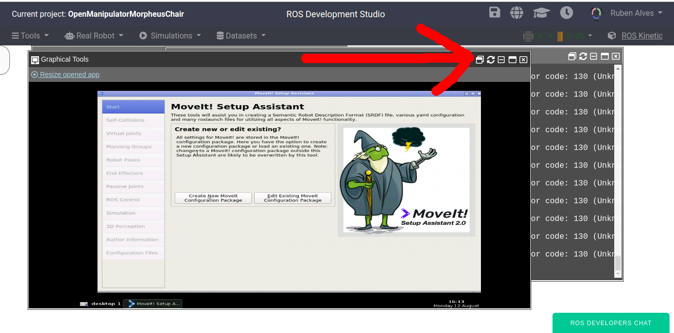
If you want the Graphical Tools to be opened in a different tab of the web browser, you can simply click on the Detach button as shown below:
Creating the MoveIt package from scratch
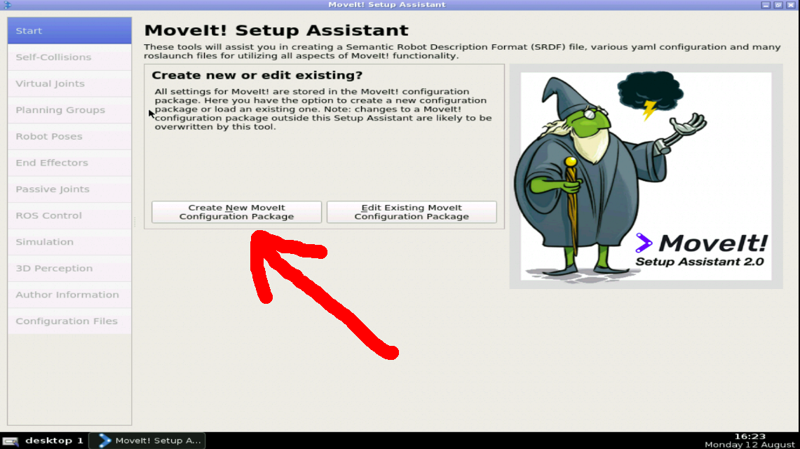
With the MoveIt Assistant open, let’s click on the Create New MoveIt Configuration Package button as shown in the image below:
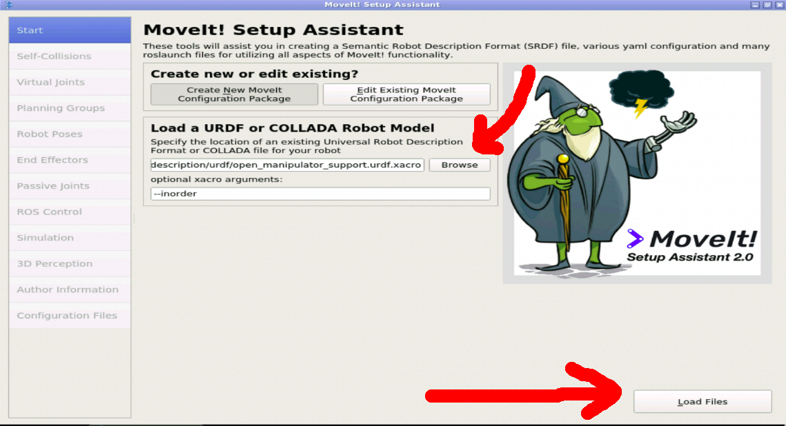
Now we need to select our URDF file. For that, let’s click on the Browse button under the section Load a URDF or Collada Robot Model and select our URDF file mentioned earlier, which is on the path:
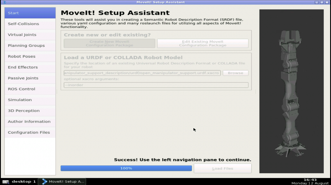
then let’s click Load Files as in the image below.
Now you should have the URDF loaded. Make sure you can see it properly as in the right side of the image below:
Generate Collision Matrix
The first thing that is vital for a robot arm when it moves, is to NOT HIT ITSELF. Which seems dumb but, it is really a common way to break a thousand-euros robot arm if it doesn’t have the correct safety features like peak torque detection or some kind of external perception.
We have to generate what is called Self-Collision Matrix. To do it we use the Self-Collision Matrix Generator. We need to generate this matrix because:
Doing this we detect which links will collide with each other when moving.
We will detect also the links which will never collide with each other, which then we can remove the auto collisions calculations for them, lowering the burden in the processing.
Detect which links will be always in collision and therefore we suppose that its normal and therefore we also disable the calculations.
Disable also the links adjacent in the kinematic chain which obviously we will disable also their auto collisions.
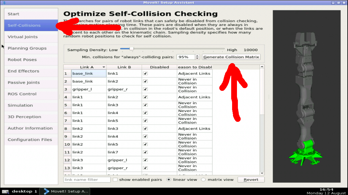
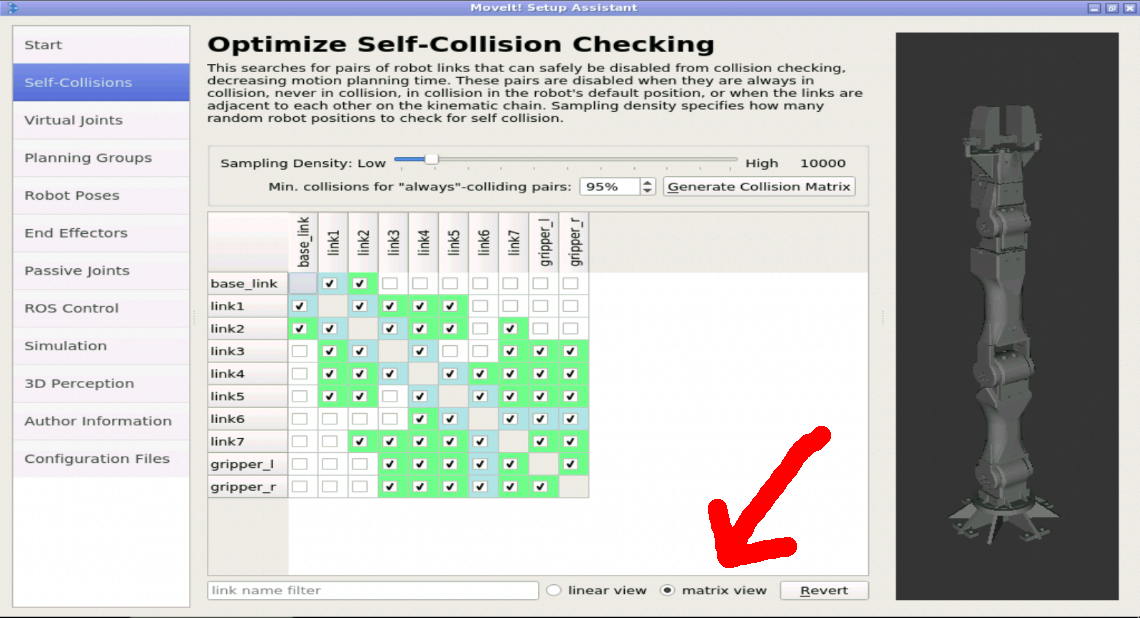
If you look on the left side image above, we are at the Start section. Let’s click on the Self-Collisions button that appears on the left and then click Generate Collision Matrix.
The buttons we clicked are shown below:
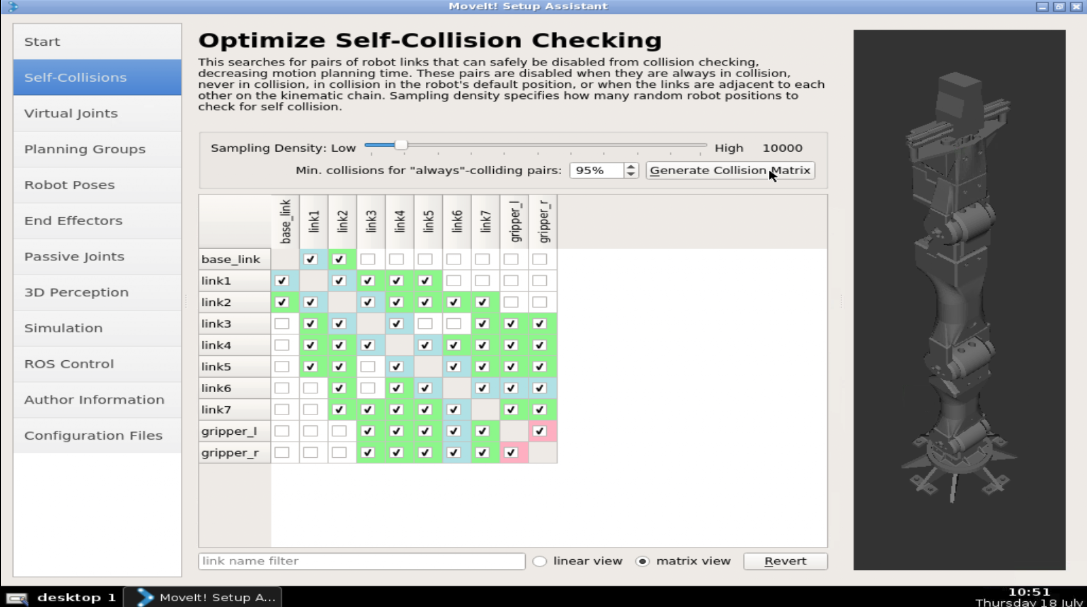
The Sampling Density value of 10,000 collision means how many random robot positions to check for self-collision. The higher the better collision detection matrix it generates, but we will need more time and processing power in parallel.
The Min Collisions of 95% means that for considering that the pair is always colliding has to be 95% of all the random positions tested.
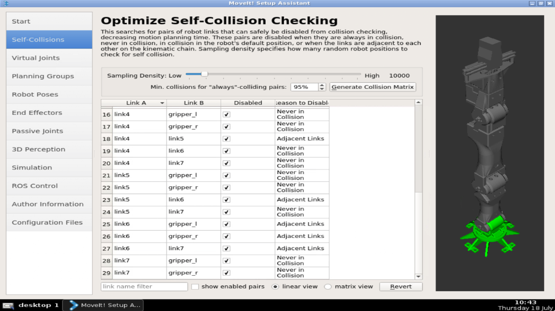
After clicking Generate Collision Matrix we have the matrix generated as in the image below.
The links are listed in a Linear View. Let’s select the Matrix View because that view allows a better understanding.
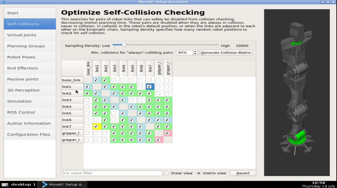
The green parts of the image above means “Never Collide”.
Note that because the Collision Matrix is random, it could be that every time you generate a new matrix, the matrix appears a bit different:
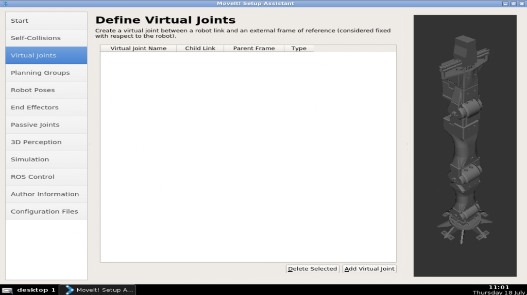
Virtual Joints
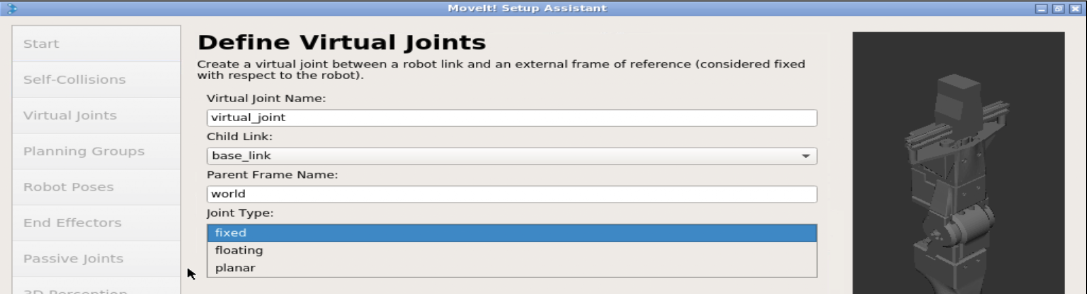
A robot that moves around a plane is specified using a planar virtual joint that connects the world frame to the frame of the robot. A robot that doesn’t move, will use a fixed joint to connect the base frame to the world.
In our case we select:
Name: virtual_joint ( just to know its a virtual joint )
Parent: world
Child: the base_link, that we want to connect to world.
Joint Type: Fixed, because we won’t move.
You can play with this because, what if we select as a parent a link of another robot, like a turtlebot that moves around? These things we will go deeper when the time comes. DONT FORGET TO HIT SAVE.
Planning Groups
Doing Inverse Kinematics is computationally very intensive. This means that the simpler the kinematics to solve the better. That’s why normally we divide a robot into the maximum parts that allow a correct and easy IK calculation. Ex: a robot with TWO arms, normally will be divided into LEFT_ARM and RIGHT_ARM, because we don’t need to solve inverse kinematics for both, but it all depends on the use case.
We will choose the following:
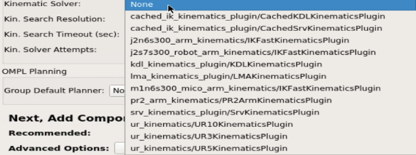
Solver: kdl_kinematics_plugin/KDLKinematicsPlugin as the kinematics solver. This is the plugin in charge of calculating the inverse kinematics. It’s a generic Kinematic solver, that will be ok for now. It is the default one in Moveit!. It only works with Serial Kinematics Chains ( tensegrities and things like that won’t work).
Name: openmanipulator_arm seems appropriate.
Kin Solv. Attempts: 3 seems reasonable.
Planner: for now we leave this none
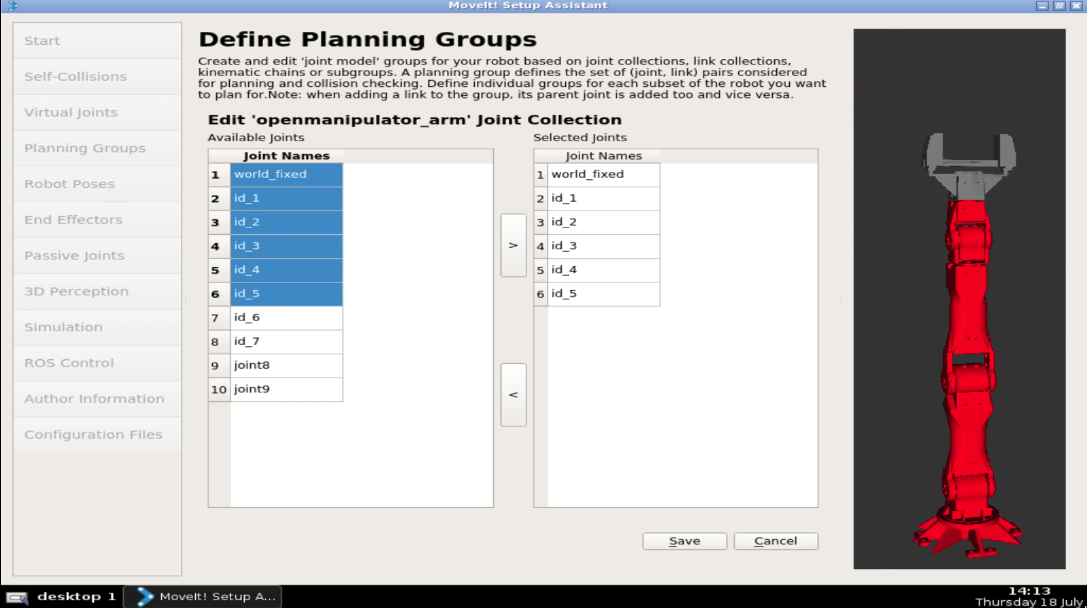
We add the joins!
In our case, we select ALL the Joints except the gripper.
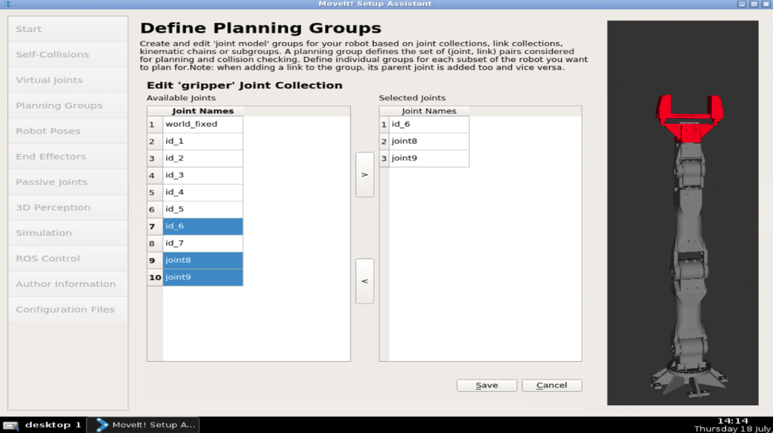
Now we add the gripper through joints also:
joint8
joint9
id_6
NOTE that we are NOT adding anywhere the LINK7 that’s because it serves no purpose in the planning for the moment.
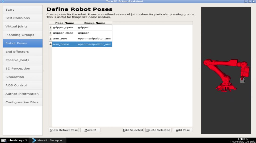
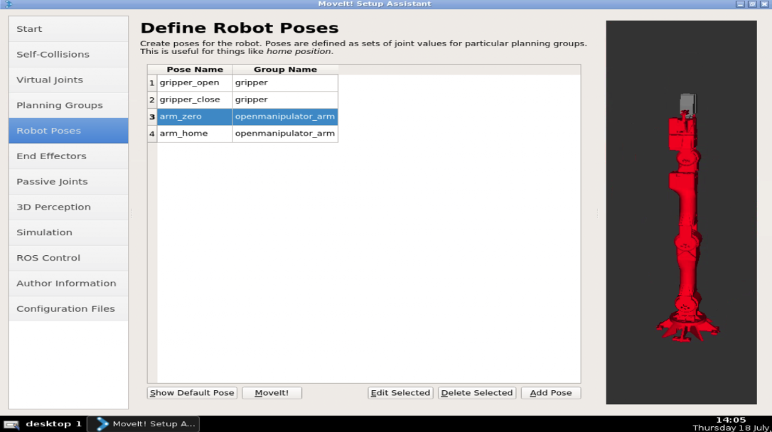
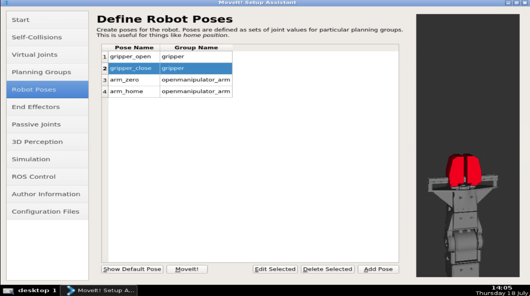
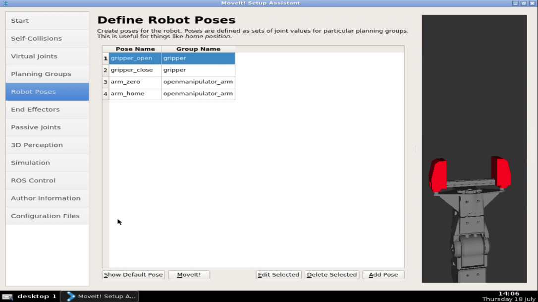
We now can store premade robot poses to set the robot in safe positions, calibration, very used positions, etc.
We added four poses:
Two for the OpenManipulator_ARM group
Two for the Gripper group.
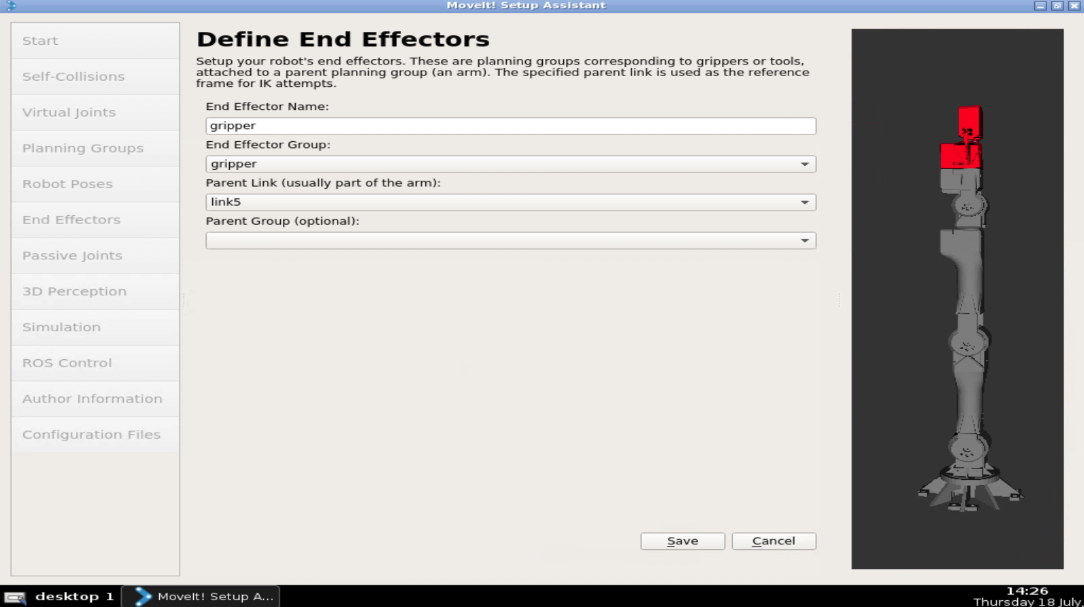
End Effector:
We can add now the gripper as end-effector. This unblocks some functionality related exclusively with end effectors:
We set:
Name: gripper
Group ENDEffector: gripper
Parent Link: Link5
Parent Group: Not necessary here to state it.
Things we won’t set:
These are elements that we might enable after, but for now, we leave them unset because we don’t need them:
Passive Joints: These are for caster wheels and other arent actuated.
3D perception: We don’t have for the moment any sensors (We mey add it afterwards).
Simulation: When executed it tells us there is nothing to change.
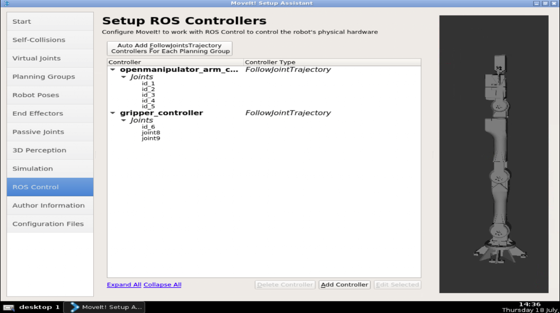
ROS controllers:
Here we have two options:
Add the controllers manually: This allows us to select which type of control we are adding.
Auto-add FollowTrajectoryControll
For the moment we will AutoGenerate the FollowJointTrajectory Control. If we need to change it we just have to re-edit the Moveit package.
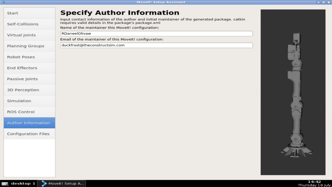
Author: Add the Author info
FINALLY, generate the package
Now is the time to generate the package that we will use:
Select the location. Hit browse and create a new folder with the name of the package you want. In our case, we will call it open_manipulator_morpheuschair_movit_config.
So, that is the post for today. We hope you guys enjoyed it. Remember that we also have a video showing everything that is in this post. Please have a look at the video if you didn’t understand some of the things that were explained here. If you liked the content, please subscribe to our channel and leave your comments on the comments section of the video, which is available at:


![[Morpheus Chair] Gazebo Simulation with MoveIt! for your Robot Arm | S4.Ep.4](https://www.theconstruct.ai/wp-content/uploads/2019/08/Gazebo-Simulation-with-MoveIt-for-your-Robot-Arm.png)
![[Morpheus Chair] Move Robot Arm with MoveIt! | S4.Ep.4](https://www.theconstruct.ai/wp-content/uploads/2019/07/Move-Robot-Arm-with-MoveIt-tutorial.png)
![[Morpheus Chair] MoveIt! for your Robot Arm | S4.Ep.3](https://www.theconstruct.ai/wp-content/uploads/2019/07/MoveIt-for-your-Robot-Arm.png)