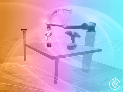
Why I Choose ROS  for My Master Thesis

Why I Choose ROS for My Master Thesis

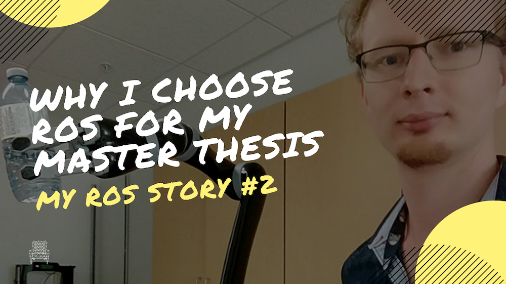
What follows is the ROS story of Simon Steinmann from Canada. Simon is a ROS student at the Robot Ignite Academy, and he wanted to share his ROS engagement with all of us.

What is ROS

Before going into details about my Thesis and my reasons for using ROS, let me give a quick explanation or recap to what ROS actually is, for all of those who are not familiar with the subject.

ROS stands for Robot Operating System and is actually not a real operating system, rather a meta-operating system or environment. The big strength of ROS and its main operating principle is connecting different nodes together.

The power of ROS Nodes

Nodes are pieces of software and can be written in C++ or Python, making it really easy and accessible for most people. This way the functionality of a robot can be split into many little subsets of tasks. For example, we can have a node for controlling servo motors, nodes to read sensors and a node that contains controlling algorithms. All these nodes can talk to one another by using ROS’s publish and subscribe protocol. This is done using topics.

Imagine nodes being workers in an office, and topics being like blackboards in the hallway, which every worker can post information onto, and read the information of others, who have posted there. So, for example, a sensor node can post a topic containing the sensor data, and every node that needs that data can subscribe to that topic to get the data. There is a bit more to it, but that is the basic working principle, and it is a very simple and powerful one.

As mentioned before, one of those advantages is that different nodes can be written in either C++ or Python and work flawlessly together. Another great thing is the ability to have nodes running on different hardware. All we need is for them to be connected by a network. So, for example, we can have the nodes controlling the servos and reading sensors, directly running on the robot (like a drone), while the more complex controlling nodes and algorithms run one or several computers. It even enables you to control a robot from anywhere in the world, simply by setting up a VPN.

ROS – a must have skill for robotics developer

ROS is also open source and thus free, with a huge following and the excellent documentation and resources online. Robotics is a booming field in engineering, and with the advent of quadcopter and consumer drones in recent years, it has become a very accessible hobby with a low barrier to entry. However, ROS is not just for hobbyists, it is widely utilized in existing industry and the countless new robotics companies. This makes learning ROS almost a must if you are considering to become a robotics developer.

What do I plan on using ROS for?

I am currently studying Aerospace Engineering at the University of Stuttgart in Germany. However, my master thesis is in robotics and a cooperation between DLR (Deutsches Zentrum für Luft- und Raumfahrt, German Aerospace Agency) and the University of British Columbia. The goal is to develop a scalable method to train a set of Reinforcement Learning algorithms with the use of a digital twin. Once a task is “learned”, it is then to be implemented into the physical system, e.g. for production.

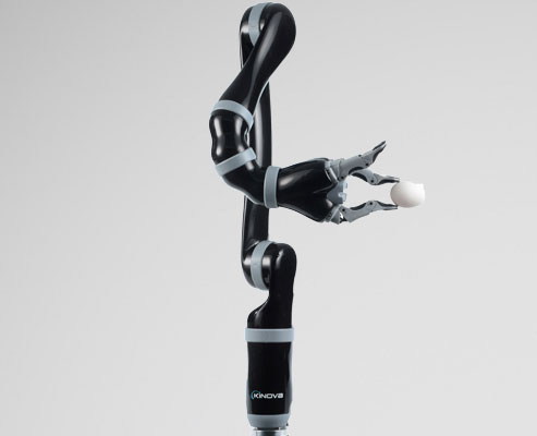
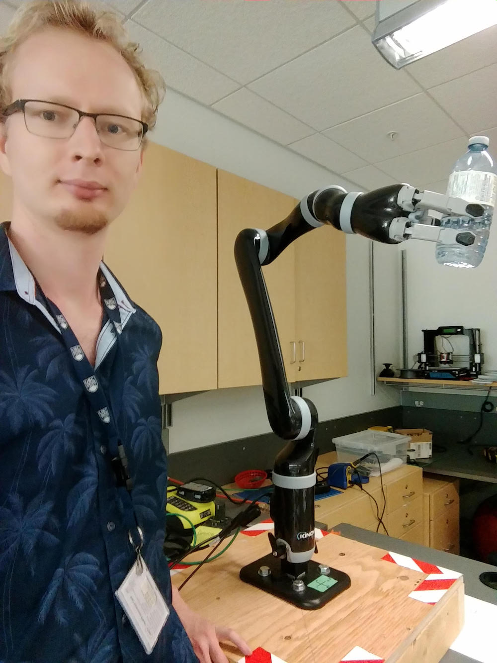
My Method is to be independent of the robot and task and scalable to a multitude of applications. In order to make things less complicated, I am working with the JACO2 Robot from KINOVA, which is a 6 DOF gripper robot.

JACO2 Robot from Kinova

JACO2 Robot from KINOVA

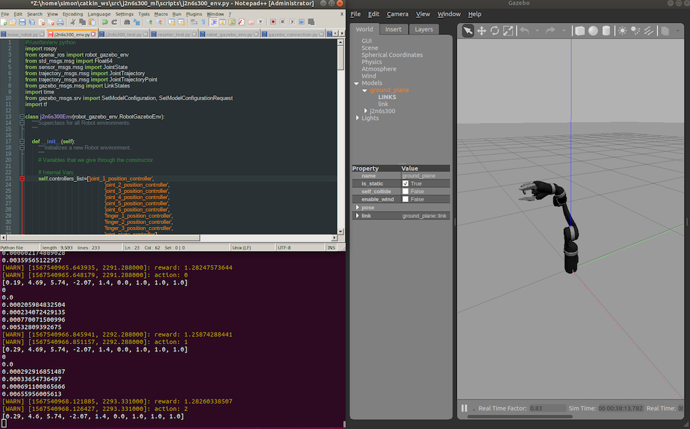
The robot simulation is set up in gazebo. Both, the simulation and the physical robot, can be controlled via ROS. So in a first step, I plan to use ROS to communicate between the simulation and the machine learning algorithms, which I shall call the “brain”. The simulation provides and publishes all relevant position and sensor data, just like the real robot would, and the brain sends commands to the simulation. All this is done using ROS, nodes, and topics. Once the brain has learned a task in the simulation, it will then connect to the real robot, using ROS to send its commands to the robot. Since both simulating a robot and its interaction with objects with physics, as well as training machine learning algorithms is very CPU intensive, the ability to spread the workload over different machines with ROS comes in very handy. The goal is to have the machine learning run on one workstation, and the simulation on another. This was fairly straight forward to set up and didn’t require a lot of networking knowledge. Simply setting up a VPN between the machines and telling the 2nd computer to listen to the primary computer instead to its own localhost.

KINOVA, like many other robot manufacturers, already provides the controllers which can be easily implemented with ROS. This makes ROS an excellent choice for my thesis as a multitude of robots already use ROS.  Furthermore, it natively supports c++ and python, making it incredibly easy to develop and to implement other software. Especially the compatibility with OpenAI Gym makes ROS a perfect choice for my work and any machine learning or reinforcement learning tasks.

Why did I consider Robot Ignite Academy as the best place to learn ROS?

Recently starting using and working with ROS made me realize how powerful and versatile it is, and I wish I would have been introduced to it earlier. I first came across the Robot Ignite Academy when researching how to make Gazebo and OpenAI Gym work together. I tried to implement their openai-ros package, which in theory is easy. However, having a non-natively supported robot, it quickly became apparent that I was lacking the skills and knowledge to efficiently tackle my problems. While the documentation for ROS on the internet is great and there are many tutorials, they are usually spread apart and it is hard to know what you have to know and where to start.

Having struggled for over a month getting our robot to run under ubuntu 18.04 and ROS melodic and constantly running into little hiccups and errors which require a lot of research, the already set up training environments in the Robot Ignite Academy sounds like a godsend and considerably less headaches trying to fix random errors and package incompatibilities in Linux. So I am looking forward to become a ROS developer in a quick and efficient manner. And while my field of study is Aerospace Engineering, with a focus on Space and Aircraft Propulsion, I am fascinated by AI, machine learning, robotics and Industry 4.0. All these areas are playing a rapidly increasing roll in my field of studies. And while I am not planning to become a pure ROS developer, I see learning and understanding ROS as a vital toolset for myself and anyone who plans to go into similar positions. In Industry 4.0 everything will be connected, and robotics will play a major role.

I want to be ready for that.

My Robotic Manipulator #04: URDF/Transmission + Gazebo Controllers

My Robotic Manipulator #04: URDF/Transmission + Gazebo Controllers

URDF/Transmission + Gazebo Controllers

Hey ROS developers! In this post, we will make our robot able to be spawned into Gazebo simulator. Based on the YouTube video series, we’ll show in this format the steps to achieve the final result of the series!

In this post number #4, I’m gonna create the Transmissions and controllers to some of our joints using the same XACROs files we have been working with. Up to the end of the post, we’ll have part of our model controllers by gazebo controllers!


Step 1 – Simplifying the robot

It turns out we have a very complex robot, with 6 links and 5 joints. I want to make it simpler in order to show how to use gazebo controller plugin.

Let’s start opening the file mrm.xacro and comment leave only the first links of the robot (the rest, we will comment). It will look like below:

<?xml version="1.0" ?>

<robot name="mrm" xmlns:xacro="http://www.ros.org/wiki/xacro">

  <!-- BGN - Include -->
  <xacro:include filename="$(find mrm_description)/urdf/links_joints.xacro" />
  <xacro:include filename="$(find mrm_description)/urdf/robot_parameters.xacro" />
  <!-- END - Include -->

  <!-- BGN - Robot description -->
  <m_link_box name="${link_00_name}"
           origin_rpy="0 0 0" origin_xyz="0 0 0"
           mass="1024"
           ixx="170.667" ixy="0" ixz="0"
           iyy="170.667" iyz="0"
           izz="170.667"
           size="1 1 1" />

  <m_joint name="${link_00_name}__${link_01_name}" type="revolute"
           axis_xyz="0 0 1"
           origin_rpy="0 0 0" origin_xyz="0 0 0.5"
           parent="${link_00_name}" child="${link_01_name}" />

  <m_link_cylinder name="${link_01_name}"
           origin_rpy="0 0 0" origin_xyz="0 0 0.2"
           mass="157.633"
           ixx="13.235" ixy="0" ixz="0"
           iyy="13.235" iyz="0"
           izz="9.655"
           length="0.4" radius="0.35" />

  <m_joint name="${link_01_name}__${link_02_name}" type="revolute"
           axis_xyz="0 1 0"
           origin_rpy="0 0 0" origin_xyz="0 0 0.4"
           parent="${link_01_name}" child="${link_02_name}" />

  <m_link_cylinder name="${link_02_name}"
           origin_rpy="0 0 0" origin_xyz="0 0 0.4"
           mass="57.906"
           ixx="12.679" ixy="0" ixz="0"
           iyy="12.679" iyz="0"
           izz="0.651"
           radius="0.15" length="0.8" />

<!--
  <m_joint name="${link_02_name}__${link_03_name}" type="revolute"
           axis_xyz="0 1 0"
           origin_rpy="0 0 0" origin_xyz="0 0 0.8"
           parent="${link_02_name}" child="${link_03_name}" />

  <m_link_cylinder name="${link_03_name}"
           origin_rpy="0 0 0" origin_xyz="0 0 0.4"
           mass="57.906"
           ixx="12.679" ixy="0" ixz="0"
           iyy="12.679" iyz="0"
           izz="0.651"
           radius="0.15" length="0.8" />

  <m_joint name="${link_03_name}__${link_04_name}" type="revolute"
           axis_xyz="0 1 0"
           origin_rpy="0 0 0" origin_xyz="0 0 0.8"
           parent="${link_03_name}" child="${link_04_name}" />

  <m_link_cylinder name="${link_04_name}"
           origin_rpy="0 0 0" origin_xyz="0 0 0.4"
           mass="57.906"
           ixx="12.679" ixy="0" ixz="0"
           iyy="12.679" iyz="0"
           izz="0.651"
           radius="0.15" length="0.8" />

  <m_joint name="${link_04_name}__${link_05_name}" type="revolute"
           axis_xyz="0 0 1"
           origin_rpy="0 0 0" origin_xyz="0 0 0.8"
           parent="${link_04_name}" child="${link_05_name}" />

  <m_link_cylinder name="${link_05_name}"
           origin_rpy="0 0 0" origin_xyz="0 0 0.125"
           mass="18.056"
           ixx="0.479" ixy="0" ixz="0"
           iyy="0.479" iyz="0"
           izz="0.204"
           radius="0.15" length="0.25" />
-->
  <!-- END - Robot description -->

</robot>

Start an empty world simulation and launch the robot from a web shell:

roslaunch mrm_description spawn.launch

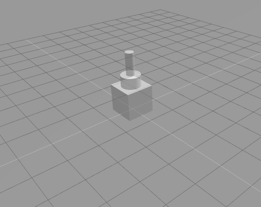
Great! These are the parts we are going to control!


Step 2 – Adding gazebo controller dependencies

We need to modify two of our package files, in order to include the dependencies. They are:

CMakeLists.txt

In the command find_package, let’s add some new values:

find_package(catkin REQUIRED COMPONENTS
  urdf
  controller_manager
  joint_state_controller
  robot_state_publisher
)

And in the package.xml file, make sure you have the following instructions:

  <build_depend>urdf</build_depend>
  <build_depend>controller_manager</build_depend>
  <build_depend>joint_state_controller</build_depend>
  <build_depend>robot_state_publisher</build_depend>

  <build_export_depend>urdf</build_export_depend>
  <build_export_depend>controller_manager</build_export_depend>
  <build_export_depend>joint_state_controller</build_export_depend>
  <build_export_depend>robot_state_publisher</build_export_depend>

  <exec_depend>urdf</exec_depend>
  <exec_depend>controller_manager</exec_depend>
  <exec_depend>joint_state_controller</exec_depend>
  <exec_depend>robot_state_publisher</exec_depend>


Step 3 – Adding transmissions to the robot model

Next thing, we need some transmissions elements in our robot model.

Let’s get back to the URDF file: mrm.xacro

  <m_link_box name="${link_00_name}"
           origin_rpy="0 0 0" origin_xyz="0 0 0"
           mass="1024"
           ixx="170.667" ixy="0" ixz="0"
           iyy="170.667" iyz="0"
           izz="170.667"
           size="1 1 1" />

  <m_joint name="${link_00_name}__${link_01_name}" type="revolute"
           axis_xyz="0 0 1"
           origin_rpy="0 0 0" origin_xyz="0 0 0.5"
           parent="${link_00_name}" child="${link_01_name}" />

  <transmission name="trans_${link_00_name}__${link_01_name}">
    <type>transmission_interface/SimpleTransmission</type>
    <joint name="${link_00_name}__${link_01_name}">
        <hardwareInterface>hardware_interface/EffortJointInterface</hardwareInterface>
    </joint>
    <actuator name="motor_${link_00_name}__${link_01_name}">
        <hardwareInterface>hardware_interface/EffortJointInterface</hardwareInterface>
        <mechanicalReduction>1</mechanicalReduction>
    </actuator>
  </transmission>

  <m_link_cylinder name="${link_01_name}"
           origin_rpy="0 0 0" origin_xyz="0 0 0.2"
           mass="157.633"
           ixx="13.235" ixy="0" ixz="0"
           iyy="13.235" iyz="0"
           izz="9.655"
           length="0.4" radius="0.35" />

  <m_joint name="${link_01_name}__${link_02_name}" type="revolute"
           axis_xyz="0 1 0"
           origin_rpy="0 0 0" origin_xyz="0 0 0.4"
           parent="${link_01_name}" child="${link_02_name}" />

  <transmission name="trans_${link_01_name}__${link_02_name}">
    <type>transmission_interface/SimpleTransmission</type>
    <joint name="${link_01_name}__${link_02_name}">
        <hardwareInterface>hardware_interface/EffortJointInterface</hardwareInterface>
    </joint>
    <actuator name="motor_${link_01_name}__${link_02_name}">
        <hardwareInterface>hardware_interface/EffortJointInterface</hardwareInterface>
        <mechanicalReduction>1</mechanicalReduction>
    </actuator>
  </transmission>

  <m_link_cylinder name="${link_02_name}"
           origin_rpy="0 0 0" origin_xyz="0 0 0.4"
           mass="57.906"
           ixx="12.679" ixy="0" ixz="0"
           iyy="12.679" iyz="0"
           izz="0.651"
           radius="0.15" length="0.8" />

You can notice we have added a new element with the transmission tag.

What are we describing there?

First, we have a transmission for each joint. Then we define the type of the transmission, which in this case is just a SimpleTransmission.

Then, the joint we are referencing with the transmission.

Further, the actuator type, which is an Effort Joint Interface, in this case. And the mechanical reduction.

We do this for both joints we have left (in this simplified version of the robot).


Step 4 – Setup gazebo controllers on URDF model

Still on the same file, let’s add to the end of the description the tags related to gazebo controller plugin.

Just simple as below, append to the end of the file, just before the </robot>:

<gazebo>
    <plugin name="gazebo_ros_control" filename="libgazebo_ros_control.so">
    </plugin>
</gazebo>


Step 5 – Describe controller YAML file

This is something necessary for the gazebo controller, we must define some control variables (PID) to apply to our transmissions.

In order to do that, let’s create a new file: ~/simulation_ws/src/mrm_description/config/joints.yaml

It goes like that:

# Publish all joint states -----------------------------------
joint_state_controller:
  type: joint_state_controller/JointStateController
  publish_rate: 50

# Position Controllers ---------------------------------------
joint1_position_controller:
  type: effort_controllers/JointPositionController
  joint: base_link__link_01
  pid: {p: 2000.0, i: 100, d: 500.0}
joint2_position_controller:
  type: effort_controllers/JointPositionController
  joint: link_01__link_02
  pid: {p: 50000.0, i: 100, d: 2000.0}

We are defining the joint_state_publisher as reference.

Then tuning each one of the transmissions we have defined in our model. We need again the nametypejoint name and the PID values


Step 6 – Launch Gazebo Controllers

Now, let’s modify our launch file.

It goes like:

<?xml version="1.0" encoding="UTF-8"?>
<launch>
    <group ns="/mrm">

        <!-- Robot model -->
        <param name="robot_description" command="$(find xacro)/xacro --inorder '$(find mrm_description)/urdf/mrm.xacro'" />
        <arg name="x" default="0" />
        <arg name="y" default="0" />
        <arg name="z" default="0.5" />

        <!-- Spawn the robot model -->
        <node name="mybot_spawn" pkg="gazebo_ros" type="spawn_model" output="screen"
            args="-urdf -param robot_description -model mrm -x $(arg x) -y $(arg y) -z $(arg z)" />

        <!-- Load controllers -->
        <rosparam command="load" file="$(find mrm_description)/config/joints.yaml" />

        <node name="controller_spawner" pkg="controller_manager" type="spawner"
              respawn="false" output="screen" ns="/mrm"
              args="--namespace=/mrm
              joint_state_controller
              joint1_position_controller
              joint2_position_controller
              --timeout 60">
        </node>
    </group>
</launch>

First main modification is the group tag, where we define a namespace (mrm) for our robot processes. Everything inside this tag inherits the namespace. It’s necessary for the controller plugin.

Then, in the secion Load controllers we have a new parameter, that loads the config.yml file we have just created.

Finally, a new node to run the controller process.


Step 7 – Testing!

Great! Now we have already configured the controllers, you can spawn the robot again! Same commands as before, but this time you will notice the last link won’t fall down! This is very important to achieve since the controllers are already actuating.

Check the shell, you can see the controllers being loaded in the logs!

process[mrm/mybot_spawn-1]: started with pid [4817]
process[mrm/controller_spawner-2]: started with pid [4822]
[INFO] [1567187158.002693, 0.000000]: Controller Spawner: Waiting for service /mrm/controller_manager/load_controller
the rosdep view is empty: call 'sudo rosdep init' and 'rosdep update'
SpawnModel script started
[INFO] [1567187165.292282, 0.000000]: Loading model XML from ros parameter
[INFO] [1567187165.303925, 0.000000]: Waiting for service /gazebo/spawn_urdf_model
[INFO] [1567187165.312998, 0.000000]: Calling service /gazebo/spawn_urdf_model
[INFO] [1567187165.504207, 904.010000]: Spawn status: SpawnModel: Successfullyspawned entity
[mrm/mybot_spawn-1] process has finished cleanly
log file: /home/user/.ros/log/cfa21f58-cb4b-11e9-9ca9-0a2504d14030/mrm-mybot_spawn-1*.log
[INFO] [1567187166.829017, 904.050000]: Controller Spawner: Waiting for service /mrm/controller_manager/switch_controller
[INFO] [1567187166.831181, 904.050000]: Controller Spawner: Waiting for service /mrm/controller_manager/unload_controller
[INFO] [1567187166.848968, 904.070000]: Loading controller: joint_state_controller
[INFO] [1567187167.000380, 904.220000]: Loading controller: joint1_position_controller
[INFO] [1567187167.268639, 904.500000]: Loading controller: joint2_position_controller
[INFO] [1567187167.345849, 904.570000]: Controller Spawner: Loaded controllers: joint_state_controller, joint1_position_controller, joint2_position_controller
[INFO] [1567187167.355672, 904.590000]: Started controllers: joint_state_controller, joint1_position_controller, joint2_position_controller

We have also new ROS topics related to the controllers:

user:~$ rostopic list
/clock
/gazebo/link_states
/gazebo/model_states
/gazebo/parameter_descriptions
/gazebo/parameter_updates
/gazebo/set_link_state
/gazebo/set_model_state
/mrm/joint1_position_controller/command
/mrm/joint1_position_controller/pid/parameter_descriptions
/mrm/joint1_position_controller/pid/parameter_updates
/mrm/joint1_position_controller/state
/mrm/joint2_position_controller/command
/mrm/joint2_position_controller/pid/parameter_descriptions
/mrm/joint2_position_controller/pid/parameter_updates
/mrm/joint2_position_controller/state
/mrm/joint_states
/rosout
/rosout_agg

As a final test, let’s send a reference to the second joint:

rostopic pub -1 /mrm/joint2_position_controller/command std_msgs/Float64 "data: 0.7"

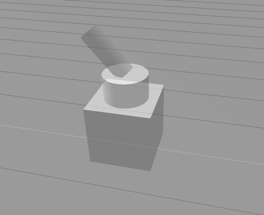
You must have the robot like:

In order to put it back to the original position, execute the command below:

rostopic pub -1 /mrm/joint2_position_controller/command std_msgs/Float64 "data: 0.0"


Related courses

Robot-creation-URDF Course Cover - ROS Online Courses - Robot Ignite Academy

URDF for Robot Modeling

ROS Manipulation Course Cover - ROS Online Courses - Robot Ignite Academy

ROS Manipulation

ROS Industrial robots Course Cover - ROS Online Courses - Robot Ignite Academy

ROS for Industrial Robots

Step 8 – Conclusion

Great! If you missed any of the steps or something just didn’t work, you can check the original project just clicking on the link: http://www.rosject.io/l/c1ed2ee/

See you in the next post!

My Robotic Manipulator #03 – URDF Inertia for Gazebo

My Robotic Manipulator #03 – URDF Inertia for Gazebo

URDF Inertia for Gazebo – Introduction

Hey ROS developers! In this post, we will make our robot able to be spawned into Gazebo simulator. Based on the YouTube video series, we’ll show in this format the steps to achieve the final result of the series!

In this post number #3, I’m gonna create the Inertia properties to each of our links using the same XACROs files we have been working with. Up to the end of the post, we’ll have the complete model of the robot inside a Gazebo world!


Step 1 – Adding Inertial and Collision properties – Adjust XACRO file

The first part of this modification is adding some new properties to the links we already have.

Let’s open the file ~/simulation_ws/src/mrm_description/urdf/links_joints.xacro

There we have XACROs being defined, one for joints and 2 others for links. The links are the ones we need to adjust:

Cylinder links

The first one, the macro called m_link_cylinder, this is how it must look like, after the adjustments:

<xacro:macro name="m_link_cylinder" params="name origin_xyz origin_rpy radius length mass ixx ixy ixz iyy iyz izz">
    <link name="${name}">
    <inertial>
        <mass value="${mass}" />
        <origin rpy="${origin_rpy}" xyz="${origin_xyz}" />
        <inertia ixx="${ixx}" ixy="${ixy}" ixz="${ixz}" iyy="${iyy}" iyz="${iyz}" izz="${izz}" />
    </inertial>
    <collision>
        <origin rpy="${origin_rpy}" xyz="${origin_xyz}" />
        <geometry>
            <cylinder radius="${radius}" length="${length}" />
        </geometry>
    </collision>
    <visual>
        <origin rpy="${origin_rpy}" xyz="${origin_xyz}" />
        <geometry>
            <cylinder radius="${radius}" length="${length}" />
        </geometry>
    </visual>
    </link>
</xacro:macro>

We added the inertial property, the one in charge of passing the mass and inertia values, from a real or project of a robot we have, to the simulator. These values are going to be used by the physics calculator of Gazebo.

And the collision property is used to calculate when an object collides to another during the simulation. Important to notice its values are the same of the visual part. That’s because we have a simple visual part for these links. It happens to have different values for visual and collision when we want to simplify the collisions for a more complex mesh we may have for a joint (we’ll have an example up to the end of the series).

Finally, don’t forget (if you are copying the new values manually) to notice the new params values we have added to the definition of the tag xacro:macro.

Box links

And for the second type of links we have, the box one. We need to do very similar modifications, but quite different parameters, due to the kind of shape we have now.

The macro must look like:

<xacro:macro name="m_link_box" params="name origin_xyz origin_rpy size mass ixx ixy ixz iyy iyz izz">
    <link name="${name}">
        <inertial>
            <mass value="${mass}" />
            <origin rpy="${origin_rpy}" xyz="${origin_xyz}" />
            <inertia ixx="${ixx}" ixy="${ixy}" ixz="${ixz}" iyy="${iyy}" iyz="${iyz}" izz="${izz}" />
        </inertial>
        <collision>
            <origin rpy="${origin_rpy}" xyz="${origin_xyz}" />
            <geometry>
            <box size="${size}" />
            </geometry>
        </collision>
        <visual>
            <origin rpy="${origin_rpy}" xyz="${origin_xyz}" />
            <geometry>
            <box size="${size}" />
            </geometry>
        </visual>
    </link>
</xacro:macro>

Again, we have added new parameters to the macro tag, which are in the value of the params attribute.

And added the inertial and collision tags, for the very same reason.


Step 2 – Adjusting the main XACRO file – mrm.xacro

Let’s open the main file we have to describe the entire robot: ~/simulation_ws/src/mrm_description/urdf/mrm.xacro

The changed we need to do are related only the new parameters we added to the MACROs. The worst part is that we’ll do one by one (which is the most important part when you have many different links from a real robot). Let’s start!

Base_link

Starting from the base_link (or ${link_00_name}, the one which is a box):

<m_link_box name="${link_00_name}"
           origin_rpy="0 0 0" origin_xyz="0 0 0"
           mass="1024"
           ixx="170.667" ixy="0" ixz="0"
           iyy="170.667" iyz="0"
           izz="170.667"
           size="1 1 1" />

The values used to fill the 7 new parameters were taken from a CAD software. It’s not something we will cover in this series, we are just bringing pre-calculated values to the practical part of simulating a robot.

Link_01

For the next link named link_01 (or ${link_01_name}), let’s do the same (very similar, at least):

<m_link_cylinder name="${link_01_name}"
           origin_rpy="0 0 0" origin_xyz="0 0 0.2"
           mass="157.633"
           ixx="13.235" ixy="0" ixz="0"
           iyy="13.235" iyz="0"
           izz="9.655"
           length="0.4" radius="0.35" />

The next 3 links (_02, _03 and _04)

These links will have the same values, so let’s do it just once:

<m_link_cylinder name="${link_0X_name}"
         origin_rpy="0 0 0" origin_xyz="0 0 0.4"
         mass="57.906"
         ixx="12.679" ixy="0" ixz="0"
         iyy="12.679" iyz="0"
         izz="0.651"
         radius="0.15" length="0.8" />

(Pay attention to the name property if you are copying and pasting!!)

The final link

And the values for the final link:

<m_link_cylinder name="${link_05_name}"
        origin_rpy="0 0 0" origin_xyz="0 0 0.125"
        mass="18.056"
        ixx="0.479" ixy="0" ixz="0"
        iyy="0.479" iyz="0"
        izz="0.204"
        radius="0.15" length="0.25" />

Step 3 – Opening it in RViz

Just before trying to simulate it, let’s make sure we didn’t break anything we had before. Let’s open it in RViz, using the same launch file we used before:

From a web shell, execute the following:

roslaunch mrm_description rviz.launch

And you must have a screen like the one below:

Great!

Step 4 – Creating a launch file

Before anything related to the simulation, we need a launch file to spawn the robot. Let’s create one:

The file will be ~/simulation_ws/src/mrm_description/launch/spawn.launch

<?xml version="1.0" encoding="UTF-8"?>
<launch>
    <param name="robot_description" command="$(find xacro)/xacro --inorder '$(find mrm_description)/urdf/mrm.xacro'" />

    <arg name="x" default="0" />
    <arg name="y" default="0" />
    <arg name="z" default="0.5" />

    <node name="mybot_spawn" pkg="gazebo_ros" type="spawn_model" output="screen"
          args="-urdf -param robot_description -model mrm -x $(arg x) -y $(arg y) -z (arg z)" />
</launch>


Step 5 – Spawning the robot into a simulation

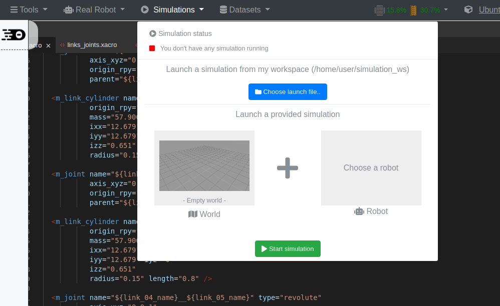
Let’s start an empty simulation from the menu:

And from a web shell, let’s spawn the robot:

<?xml version="1.0" encoding="UTF-8"?>
<launch>
    <param name="robot_description" command="$(find xacro)/xacro --inorder '$(find mrm_description)/urdf/mrm.xacro'" />

    <arg name="x" default="0" />
    <arg name="y" default="0" />
    <arg name="z" default="0.5" />

    <node name="mybot_spawn" pkg="gazebo_ros" type="spawn_model" output="screen"
          args="-urdf -param robot_description -model mrm -x $(arg x) -y $(arg y) -z $(arg z)" />
</launch>

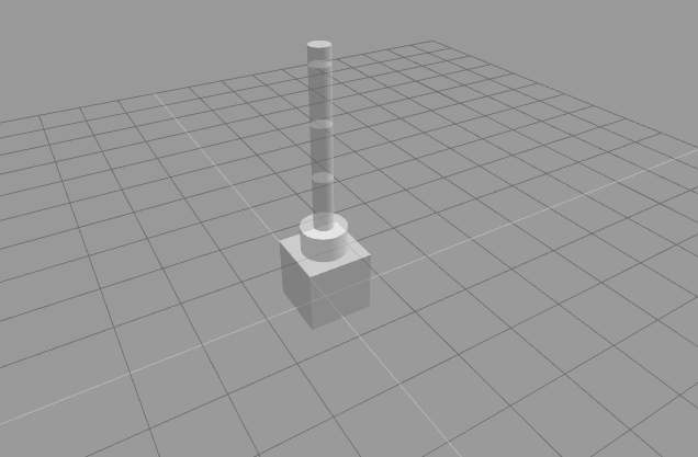
And your gazebo simulation must look like below:

After some seconds the robot will “fall down”, that’s because we didn’t aplly any controllers to the joints. (Which is something for the next post!!)

Related courses

Robot-creation-URDF Course Cover - ROS Online Courses - Robot Ignite Academy

URDF for Robot Modeling

ROS Manipulation Course Cover - ROS Online Courses - Robot Ignite Academy

ROS Manipulation

ROS Industrial robots Course Cover - ROS Online Courses - Robot Ignite Academy

ROS for Industrial Robots

Conclusion

We have created the collision and inertial parts of the robot using our XACROs! It was easy!!

In the next post, we’ll apply gazebo controllers to the robot. A very important step to have it working and controlled by our ROS programs!!

If you lost any part of the tutorial, you can get a copy of the ROSject I’ve done clicking here!

See you!


My ROS Story #1: Why I Learn ROS?

My ROS Story #1: Why I Learn ROS?

What follows is the ROS story of Shahram Najam from Pakistan. Shahram is a ROS student at the Robot Ignite Academy, and he wanted to share his ROS engagement with all of us.

Why ROS?

So, for this article, it would be appropriate to give a brief background of who I am and what are my credentials. So, my name is Shahram and I am enrolled as an undergrad student in one of the most renowned universities of Pakistan, NED University of Engineering and Technology with my major being in Electronics with a specialization in Robotics.

One of the most common questions I come across, (which evidently I had in my mind as well as beginner somewhere in time as well) is “What is ROS?” and “Why should I learn ROS?”. So these are the questions that I will be addressing in my brief article today and share my personal motivation and experience that led me down the mysterious pathways of ROS.

Why I learn ROS 1

What is ROS?

Ever since its inception back in 2007, the popularity and importance as a universal framework has grown exponentially and now the ROS community is based on researchers and hobbyists alike. Everyone irrespective of their background is mesmerized by the “Esoteric-World” of ROS. So it would only be fair to introduce ROS in the simplest of manner.

ROS is an acronym of “Robotics Operating System”. It is obviously not your traditional “Operating System” like Microsoft Windows, Linux or Mac OS, rather it is a “meta-operating system” for a robot (Aerial robots/drones, Humanoid Robots, UGV, etc.), which provides relevant services one would expect from an OS to control and communicate between the various components of the robot to function seamlessly. In short, ROS is a flexible and universal framework for writing and publishing software for robots. Due to its vast community there are readily available libraries and tools that could be used as “out of the box” solutions that could be used across a wide variety of platforms for emulating robust and composite behavior of robots i.e. the concept of ROS was conceived with only one thing in mind, and that was to make the robotic software reusable across various platforms without being interlaced with the hardware of any specification.

Why ROS is the best option to become a robotics developer?

In the modern-day and age of computer, practically everything is being taken over by computers for automation; and the backend for any of these systems there exists a robust software. For those who have been a part of software development would opt with my point that software development can be quite a time consuming, and that is why most of us try to utilize the readily available frameworks that offer tools and conventions to streamline and speed up the development process and be unobtrusive, modular and efficient.

Likewise, before the advent of ROS, most of the time during research projects was invested in re-implementing the software infrastructure such as drivers for embedded electronics, actuators and sensor networks, defining communication protocols etc. for formulating algorithm for advancements in robotics research and very brief period of time was actually dedicated towards the actual research for intelligent algorithms for intelligent robots.

ROS is nothing short of a miracle and time-saver for any robotics developer in this era of robotics. The ROS community has sky-rocketed and now on daily basis state-of-the-art robotics tools, libraries and packages are being published and open-sourced by various researchers and industries which can be used as modular building blocks for building a robust foundation for any project and to simulate its behavior without the constraints of hardware availability and costs. This is especially a win-win situation for any robotics developer irrespective of his/her background; be it a hobbyist looking to make a savvy line follower robot using image processing and a sensor network or be it a researcher to implement the state-of-the-art mobility or control technique, presented just days before in a conference, for further improvements or be it an industry looking to implement the latest update seamlessly to its network of robots on the assembly line without cessation of production. The question isn’t “Why should I become a ROS developer” rather the question should be “Why shouldn’t I become a ROS developer?” given the strong community support and easily reproducible state-of-the-art tools available.

Why do I want to be a ROS developer & What do I plan on using ROS for?

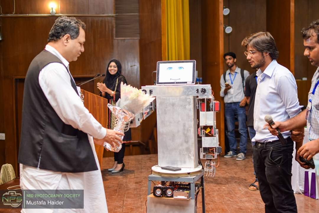
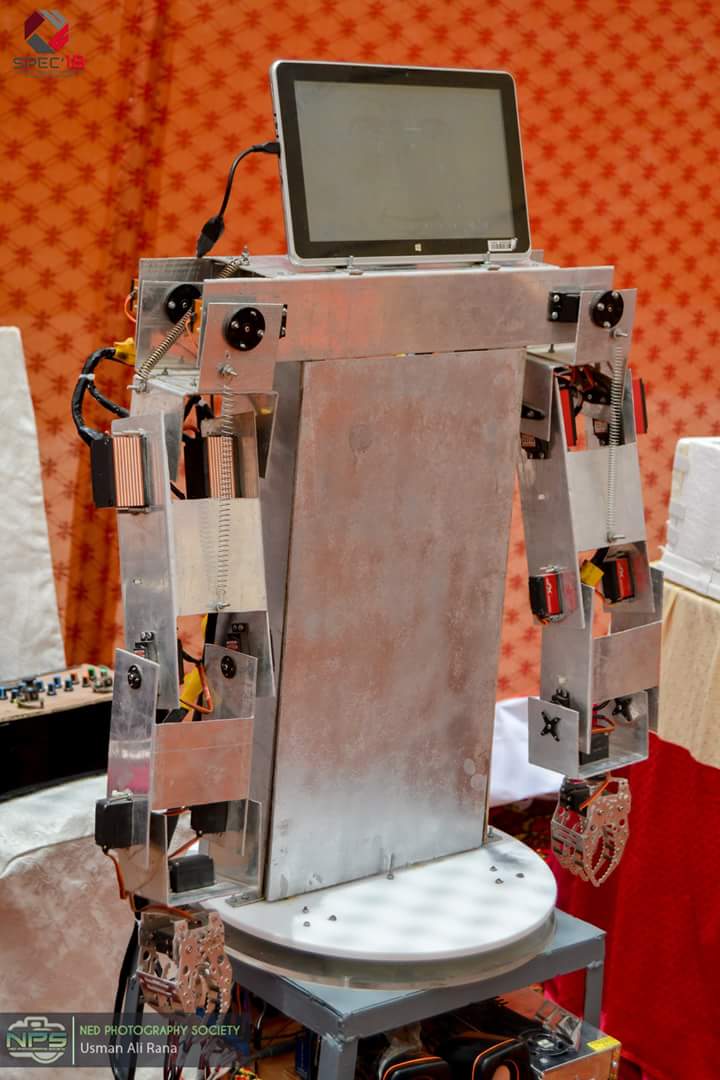
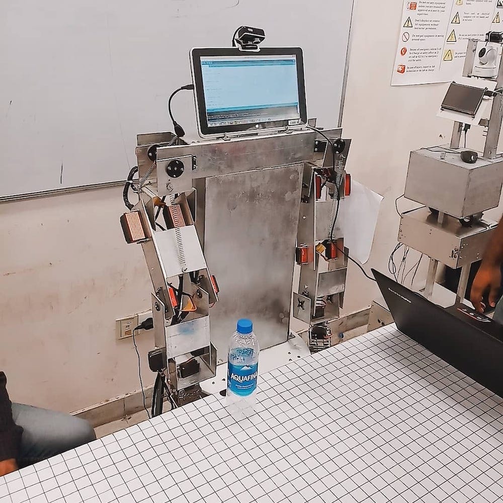
Well like many others, I have always been fascinated by robots and so this fascination and alacrity led me towards the world of embedded systems for robotics. As my capstone research project in my final year, I decided to work on Pakistan’s first-ever human-sized Humanoid Robot “I-Force” due to my obsession with human-machine interaction. Instantly I ran into a world of problems when the software development phase has begun. It was quite difficult to mix and match various tools for actuator control, image processing, etc. and to implement the state-of-the-art algorithms. So this was the time when I was desperately looking for a way out of robotics and change my specialization to something else in the domain of electronics. That’s when I came across the esoteric yet wonderful world of ROS.

Why I learn ROS I-Force 2Why I learn ROS I-Force

The more I read about ROS, the more I fell in love with it. So I decided to incorporate ROS in my humanoid robot “I-Force”. In its current state it is able to detect any object (without concept) using low-level image processing algorithm and localize its location in 3D space, this location is then used to determine the parameters like actuator position, sweep velocity, etc. using inverse kinematics technique and pick the object with the end-effector, which in my case is a claw. As a ROS developer porting the entire system onto ROS and incorporating decision making capability aided by AI to learn optimum strategies of detecting objects with context in high dimensional space state and implement Reinforcement Learning RL using the various tools that ROS has to offer. The sheer amount of data required for this is quite impractical to “teach” robot these capabilities, so a simulation on ROS could be used to train and transferring this useful “insight” from the state-of-the-art deep learning and RL models to the actual robot (this approach is readily being used for training warehouse robots, UGV, drones, etc.).

Why did I consider Robot Ignite Academy as the best place to learn ROS?

While searching for a comprehensive step-by-step tutorial for learning ROS from the ground up, I came across various books, video tutorials, and blog posts, but none were as comprehensive and exhaustive as in Robot Ignite Academy. The way clear paths are defined with a series of courses with hands-on exposure rather than just chugging down theory to reach a specific goal is truly an amazing concept, and all of this without the need of any ROS installation on a local system.


Author: Shahram Najam Syed

My Robotic Manipulator #02 – URDF + XACRO

My Robotic Manipulator #02 – URDF + XACRO

Updated 07 August 2023

What we are going to learn

  1. How to build a robot in a matter of minutes
  2. How to see the robot in RViz
  3. How to move the parts of the robot using Joint State Publisher

List of resources used in this post

  1. Use the rosject: https://app.theconstructsim.com/l/bc1c398/
  2. The Construct: https://app.theconstructsim.com/
  3. My Robot Manipulator repository: https://bitbucket.org/theconstructcore/my-robotic-manipulator
  4. ROS Courses:
    1. URDF for Robot modeling: https://app.theconstructsim.com/Course/13
  5. ROS2 Courses:
    1. URDF for Robot Modeling in ROS2 : https://app.theconstructsim.com/courses/83
    2. ROS2 Basics in 5 Days Humble (Python): https://app.theconstructsim.com/Course/132
    3. ROS2 Basics in 5 Days Humble (C++): https://app.theconstructsim.com/Course/133

Overview

Based on the YouTube video series, we’ll learn in this post the steps to achieve the final result of the series!

In this post number #2, I’m gonna show how to use XACROs in order to simplify a URDF file. Up to the end of the post, we’ll have the complete model of the robot, which includes 6 links in total, and visualize it in RViz!

This post is basically a continuation of what we saw in Post 1: https://www.theconstruct.ai/ros-projects-robotic-manipulator-part-1-basic-urdf-rviz/

ROS Inside!

ROS Inside

ROS Inside

Before anything else, if you want to use the logo above on your own robot or computer, feel free to download it and attach it to your robot. It is really free. Find it in the link below:

ROS Inside logo

Opening the rosject

In order to follow this tutorial, we need to have ROS installed in our system, and ideally a ROS Workspace (it can be named simulation_ws). To make your life easier, we have already prepared a rosject with a simulation for that: https://app.theconstructsim.com/l/bc1c398/.

You can download the rosject on your own computer if you want to work locally, but just by copying the rosject (clicking the link), you will have a setup already prepared for you.

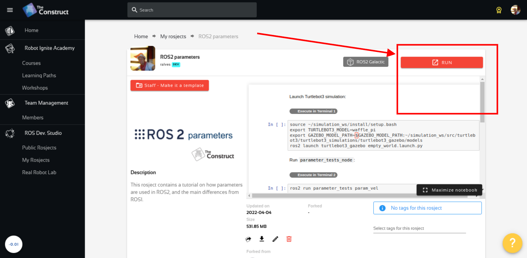
After the rosject has been successfully copied to your own area, you should see a Run button. Just click that button to launch the rosject (below you have a rosject example).

Learn ROS2 Parameters - Run rosject

My Robotic Manipulator #2: Basic URDF & RViz – Run rosject (example of the RUN button)


After pressing the Run button, you should have the rosject loaded. Now, let’s head to the next section to get some real practice.

Open a terminal

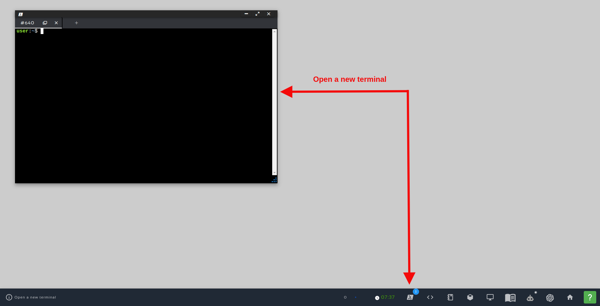
In order to create files, and launch ROS nodes, we need a terminal. Let’s open a terminal by clicking the Open a new terminal button.


Open a new Terminal

Open a new Terminal

Next step – Create some MACROs to help

Having opened the first terminal, let’s now proceed with the other parts of this tutorial

We have already created some links and a joint in the previous post. Now we need to create more of them, but let’s try to make it simpler, making our XACRO file cleaner.

Let’s create a new file, ~/simulation_ws/src/mrm_description/urdf/links_joints.xacro running the following commands in this first terminal :

touch ~/simulation_ws/src/mrm_description/urdf/links_joints.xacro

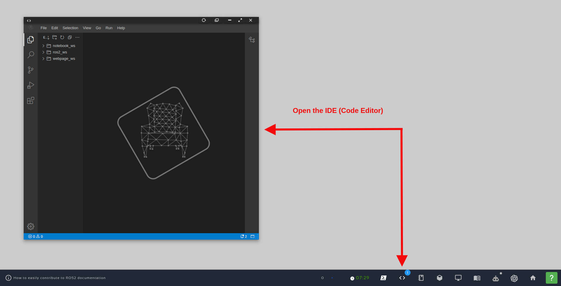
In this file, we are gonna create XML MACROs. They will help us create links and joints. Please open that file in the Code Editor, also known as IDE (Integraded Development Environment).

In order to open the IDE, just click the Code Editor button, as we can see in the image below:

Open the IDE - Code Editor

Open the IDE – Code Editor

Once the Code Editor is open, just navigate to simulation_ws/src/mrm_description/urdf/links_joints.xacro, and paste the following content to it:


<?xml version="1.0" ?>
<robot xmlns:xacro="http://www.ros.org/wiki/xacro">

    <xacro:macro name="m_joint" params="name type axis_xyz origin_rpy origin_xyz parent child">
        <joint name="${name}" type="${type}">
            <axis xyz="${axis_xyz}" />
            <limit effort="1000.0" lower="-3.14" upper="3.14" velocity="0.5" />
            <origin rpy="${origin_rpy}" xyz="${origin_xyz}" />
            <parent link="${parent}" />
            <child link="${child}" />
        </joint>
    </xacro:macro>

    <xacro:macro name="m_link_cylinder" params="name origin_xyz origin_rpy radius length">
        <link name="${name}">
            <visual>
                <origin rpy="${origin_rpy}" xyz="${origin_xyz}" />
                <geometry>
                    <cylinder radius="${radius}" length="${length}" />
                </geometry>
            </visual>
        </link>
    </xacro:macro>

    <xacro:macro name="m_link_box" params="name origin_xyz origin_rpy size">
        <link name="${name}">
            <visual>
                <origin rpy="${origin_rpy}" xyz="${origin_xyz}" />
                <geometry>
                    <box size="${size}" />
                </geometry>
            </visual>
        </link>
    </xacro:macro>
</robot>

Let’s understand what we have in this xacro file.

We have created 3 MACROs – each one with a name defined in the name attribute of the xacro:macro tags. The following attribute is used for defining the parameters we want to make available in a MACRO.

These parameters are used in the following format: ${param_name}

Let’s check how to use them in the next section.

Using our XML MACROs

In our main file, ~/simulation_ws/src/mrm_description/urdf/mrm.xacro, we have to include this new XACRO file. Let’s override its content with the following one!


<?xml version="1.0" ?>
<robot name="mrm" xmlns:xacro="http://www.ros.org/wiki/xacro"> 

    <!-- BGN - Include --> 
    <xacro:include filename="$(find mrm_description)/urdf/links_joints.xacro" />
    <!-- END - Include --> 

    <!-- BGN - Robot description --> 
    <m_link_box name="base_link" origin_rpy="0 0 0" origin_xyz="0 0 0" size="1 1 1" /> 
    <m_joint name="base_link_01" type="revolute" axis_xyz="0 0 1" origin_rpy="0 0 0" origin_xyz="0 0 0.5" parent="base_link" child="link_01" /> 
    <m_link_cylinder name="link_01" origin_rpy="0 0 0" origin_xyz="0 0 0.2" length="0.4" radius="0.35" /> 
    <!-- END - Robot description --> 

</robot>

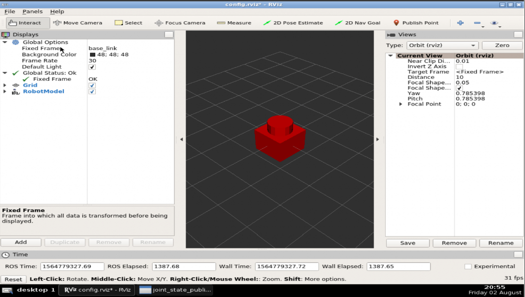
After these changes, we are now using the MACROs we have just defined, yet we must have the very same model that we had before. Let’s check it on RViz:

roslaunch mrm_description rviz.launch

The RViz window should be similar to the one in the previous post, when we did not use our own macros:

Using multiple MACRO files

In order to get used to working with MACRO files, let’s create another one. This new file will only define the name of the links and joints we are goingto have!

Let us create a new file ~/simulation_ws/src/mrm_description/urdf/robot_parameters.xacro:

touch ~/simulation_ws/src/mrm_description/urdf/robot_parameters.xacro


Now, open that file using the Code Editor, and paste the following content to it:

<?xml version="1.0" ?>
<robot xmlns:xacro="http://www.ros.org/wiki/xacro"> 

    <xacro:property name="link_00_name" value="base_link" /> 
    <xacro:property name="link_01_name" value="link_01" /> 
    <xacro:property name="link_02_name" value="link_02" /> 
    <xacro:property name="link_03_name" value="link_03" /> 
    <xacro:property name="link_04_name" value="link_04" /> 
    <xacro:property name="link_05_name" value="link_05" />
 
</robot>

Let's also include it in the main file mrm.xacro (just appending a new include to the INCLUDE section):


<!-- BGN - Include -->
<xacro:include filename="$(find mrm_description)/urdf/links_joints.xacro" />
<xacro:include filename="$(find mrm_description)/urdf/robot_parameters.xacro" /> 
<!-- END - Include -->

Finally, replace the names in the links and joints with the values we imported from the parameters file. You  must have the description part similar the one below:


 <!-- BGN - Robot description -->
 <m_link_box name="${link_00_name}" origin_rpy="0 0 0" origin_xyz="0 0 0" size="1 1 1" /> 
 <m_joint name="${link_00_name}__${link_01_name}" 
        type="revolute" 
        axis_xyz="0 0 1" 
        origin_rpy="0 0 0" 
        origin_xyz="0 0 0.5" 
        parent="${link_00_name}" 
        child="${link_01_name}" />

 <m_link_cylinder name="${link_01_name}" 
       origin_rpy="0 0 0" 
       origin_xyz="0 0 0.2" 
       length="0.4" 
       radius="0.35" 
  /> 
<!-- END - Robot description -->

With these changes, in addition to using the parameters to fill the name of the links, we also use them to compose the joint name!

Final changes on the xacro file – Finishing the robot

Let’s now create the rest of the robot! Having already defined the MACROs and link names, we now only need to reuse them by passing some arguments!

Let’s check the final content of the mrm.xacro file:

<?xml version="1.0" ?>
<robot name="mrm" xmlns:xacro="http://www.ros.org/wiki/xacro">

<!-- BGN - Include -->
<xacro:include filename="$(find mrm_description)/urdf/robot_parameters.xacro" />
<xacro:include filename="$(find mrm_description)/urdf/links_joints.xacro" />
<!-- END - Include -->

 <!-- BGN - Robot description --> 
<m_link_box name="${link_00_name}" origin_rpy="0 0 0" origin_xyz="0 0 0" size="1 1 1" /> 
<m_joint name="${link_00_name}__${link_01_name}" 
    type="revolute" 
    axis_xyz="0 0 1" 
    origin_rpy="0 0 0" 
    origin_xyz="0 0 0.5" 
    parent="${link_00_name}" 
    child="${link_01_name}" /> 

<m_link_cylinder 
    name="${link_01_name}" 
    origin_rpy="0 0 0" 
    origin_xyz="0 0 0.2" 
    length="0.4" 
    radius="0.35" /> 

 <m_joint name="${link_01_name}__${link_02_name}" 
    type="revolute" 
    axis_xyz="0 1 0" 
    origin_rpy="0 0 0" 
    origin_xyz="0 0 0.4" 
    parent="${link_01_name}" 
    child="${link_02_name}" /> 

 <m_link_cylinder name="${link_02_name}" 
    origin_rpy="0 0 0" 
    origin_xyz="0 0 0.4" 
    radius="0.15" 
    length="0.8" /> 

 <m_joint name="${link_02_name}__${link_03_name}" 
    type="revolute" axis_xyz="0 1 0" 
    origin_rpy="0 0 0" origin_xyz="0 0 0.8" 
    parent="${link_02_name}" 
    child="${link_03_name}" /> 

 <m_link_cylinder name="${link_03_name}" 
    origin_rpy="0 0 0" origin_xyz="0 0 0.4" 
    radius="0.15" 
    length="0.8" /> 

 <m_joint name="${link_03_name}__${link_04_name}" 
    type="revolute" axis_xyz="0 1 0" 
    origin_rpy="0 0 0" 
    origin_xyz="0 0 0.8" 
    parent="${link_03_name}" 
    child="${link_04_name}" /> 

 <m_link_cylinder 
    name="${link_04_name}"
    origin_rpy="0 0 0"
    origin_xyz="0 0 0.4"
    radius="0.15" 
    length="0.8" />

 <m_joint name="${link_04_name}__${link_05_name}" 
    type="revolute" 
    axis_xyz="0 0 1" 
    origin_rpy="0 0 0" 
    origin_xyz="0 0 0.8" 
    parent="${link_04_name}" 
    child="${link_05_name}" /> 

 <m_link_cylinder 
    name="${link_05_name}" 
    origin_rpy="0 0 0" 
    origin_xyz="0 0 0.125" 
    radius="0.15" 
    length="0.25" />

<!-- END - Robot description -->


  <gazebo>
    <plugin name="gazebo_ros_control" filename="libgazebo_ros_control.so">
    </plugin>
  </gazebo>
</robot>

If you want, you can explore and play with the parameters (radius and length, for example) in order to customize your own model.

Checking the robot in RViz

Alright! Having everything in place, the time now has come for seeing the robot in RViz.

Our rviz.launch may be using joint_state_publisher, but we need joint_state_publisher_gui. To solve this, let’s open that launch/rviz.launch file using the Code Editor, and replace its content with the following one:

<launch>

<param name="robot_description" command="$(find xacro)/xacro --inorder '$(find mrm_description)/urdf/mrm.xacro'"/>

<!-- Combine joint values -->
<node name="robot_state_publisher" pkg="robot_state_publisher" type="state_publisher"/>

<!-- Show in Rviz -->
<node name="rviz" pkg="rviz" type="rviz" args="-d $(find mrm_description)/launch/config.rviz" />


<!-- send joint values -->
<node name="joint_state_publisher_gui" pkg="joint_state_publisher_gui" type="joint_state_publisher_gui">
    <param name="use_gui" value="True"/>
</node>

</launch>


Now, in the first terminal, let’s launch RViz again. Remember to kill any running process that you may have in the first terminal by pressing CTRL+C first.


roslaunch mrm_description rviz.launch

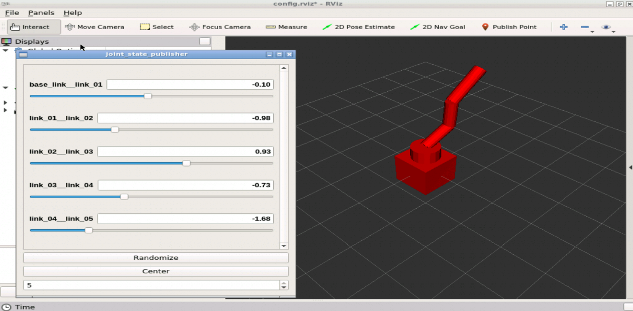
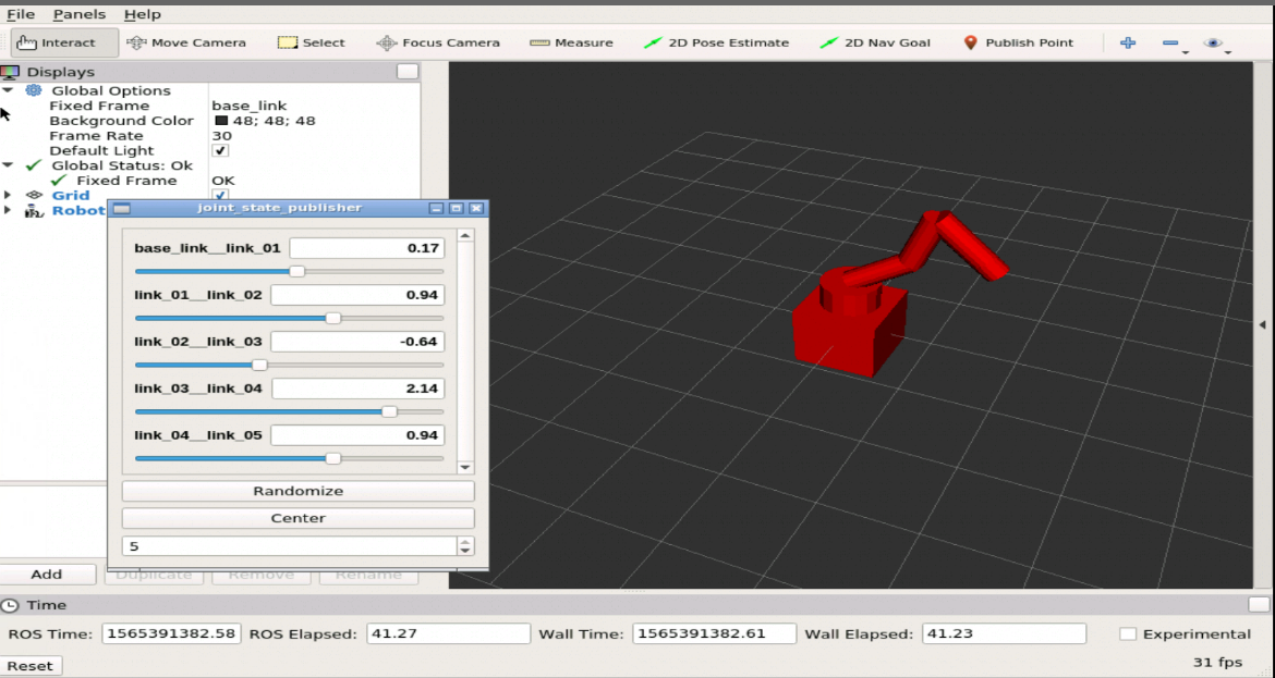
If everything went ok, you should have something similar to the following robot in RViz, after moving the joints using the Joint State Publisher :


Congratulations. We have finished the basics of a robot model using Xacro files.

In the next post, we’ll create the inertia of the robot. A very important step to have it working in Gazebo!

If you lost any part of the tutorial, you can get a copy of the ROSject, just click on this link: https://app.theconstructsim.com/l/bc1c398/

We hope this post was really helpful to you. If you want a live version of this post with more details, please check the video in the next section. Although the video was recorded in a previous version of The Construct platform, it still adds a lot of value:

Youtube video

So this is the post for today. Remember that we have the live version of this post on YouTube. If you liked the content, please consider subscribing to our youtube channel. We are publishing new content ~every day.

Keep pushing your ROS Learning.


Related Courses & Training

Robot-creation-URDF Course Cover - ROS Online Courses - Robot Ignite Academy

URDF for Robot Modeling

ROS Manipulation Course Cover - ROS Online Courses - Robot Ignite Academy

ROS Manipulation

ROS Industrial robots Course Cover - ROS Online Courses - Robot Ignite Academy

ROS for Industrial Robots

  1. ROS Courses:
    1. URDF for Robot modeling (ROS 1): https://app.theconstructsim.com/Course/13
  2. ROS2 Courses:
    1. URDF for Robot Modeling in ROS2 : https://app.theconstructsim.com/courses/83

Exploring ROS with a 2 wheeled robot #13 – GMapping

Exploring ROS with a 2 wheeled robot #13 – GMapping

Step 0 – Introduction

Hey ROS Developers!

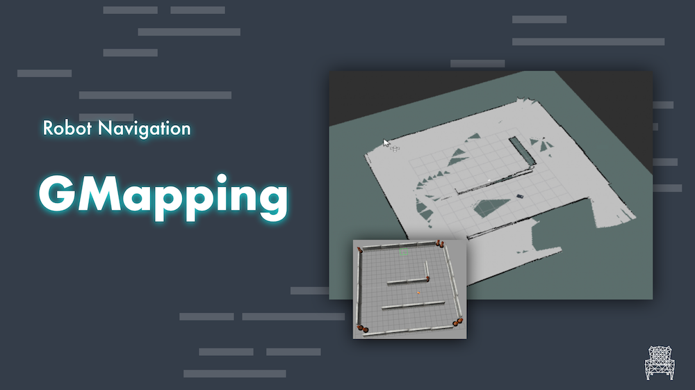
This is our last post of the series, actually a Bonus post, to show something ready-to-use ROS provides to us. The GMapping package, to create maps while our robot navigates in a given environment. We are going to show how to configure a launch file in order to use the same robot we have been using throughout this series.

Let’s start!

Step 1 – Configuring the environment

First thing, we will use the same robot in the last world we have worked. If you don’t have the ROSJect, just do a copy by clicking here

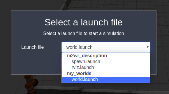
Next, launch a simulation, as we have done before:

ROS GMapping launch robot


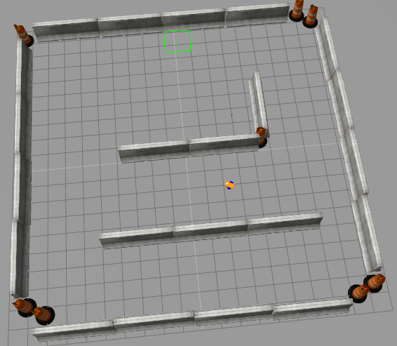
And spawn the robot using the command below in a shell:

roslaunch m2wr_description spawn y:=8

You must have the robot there, waiting to be used:

ROS GMapping robot


Step 2 – Configuring GMapping launch file

We need to create a new launch file, and I chose to do it in the motion_plan package (~/catkin_ws/src/motion_plan/launch/gmapping.launch)

The content must be the same as below, and I’ll explain the major points:

<launch>
  <arg name="scan_topic"  default="/m2wr/laser/scan" />
  <arg name="base_frame"  default="link_chassis"/>
  <arg name="odom_frame"  default="odom"/>

  <node pkg="robot_state_publisher" type="robot_state_publisher" name="robot_state_publisher"></node>

  <node pkg="rviz" type="rviz" name="rviz"></node>

  <node pkg="gmapping" type="slam_gmapping" name="slam_gmapping" output="screen">
    <param name="base_frame" value="$(arg base_frame)"/>
    <param name="odom_frame" value="$(arg odom_frame)"/>
    <param name="map_update_interval" value="5.0"/>
    <param name="maxUrange" value="6.0"/>
    <param name="maxRange" value="8.0"/>
    <param name="sigma" value="0.05"/>
    <param name="kernelSize" value="1"/>
    <param name="lstep" value="0.05"/>
    <param name="astep" value="0.05"/>
    <param name="iterations" value="5"/>
    <param name="lsigma" value="0.075"/>
    <param name="ogain" value="3.0"/>
    <param name="lskip" value="0"/>
    <param name="minimumScore" value="200"/>
    <param name="srr" value="0.01"/>
    <param name="srt" value="0.02"/>
    <param name="str" value="0.01"/>
    <param name="stt" value="0.02"/>
    <param name="linearUpdate" value="0.5"/>
    <param name="angularUpdate" value="0.436"/>
    <param name="temporalUpdate" value="-1.0"/>
    <param name="resampleThreshold" value="0.5"/>
    <param name="particles" value="80"/>
  <!--
    <param name="xmin" value="-50.0"/>
    <param name="ymin" value="-50.0"/>
    <param name="xmax" value="50.0"/>
    <param name="ymax" value="50.0"/>
  make the starting size small for the benefit of the Android client's memory...
  -->
    <param name="xmin" value="-1.0"/>
    <param name="ymin" value="-1.0"/>
    <param name="xmax" value="1.0"/>
    <param name="ymax" value="1.0"/>

    <param name="delta" value="0.05"/>
    <param name="llsamplerange" value="0.01"/>
    <param name="llsamplestep" value="0.01"/>
    <param name="lasamplerange" value="0.005"/>
    <param name="lasamplestep" value="0.005"/>
    <remap from="scan" to="$(arg scan_topic)"/>
  </node>
</launch>

The first 3 tags, the arguments, are the ones related to our robot:

  • scan_topic is the topic we have been reading to get the laser data
  • base_frame is the frame of the frame, but to be more precise, it must be the frame of the laser
  • odom_frame is the frame used by the odometry, so yes, it depends on odometry

There are other parameters you can play with (many actually), for example:

  • maxRange to set the maximum distance to use to map
  • max_update_interval that is used to improve the map updating rate (but you have to be careful with your hardware performance also)

These are the main parameters to a basic usage of gmapping. You can check the official documentation here: http://wiki.ros.org/gmapping


Step 3 – Launch Gmapping

So, let’s put it to work!

Open another shell and execute:

roslaunch motion_plan gmapping.launch

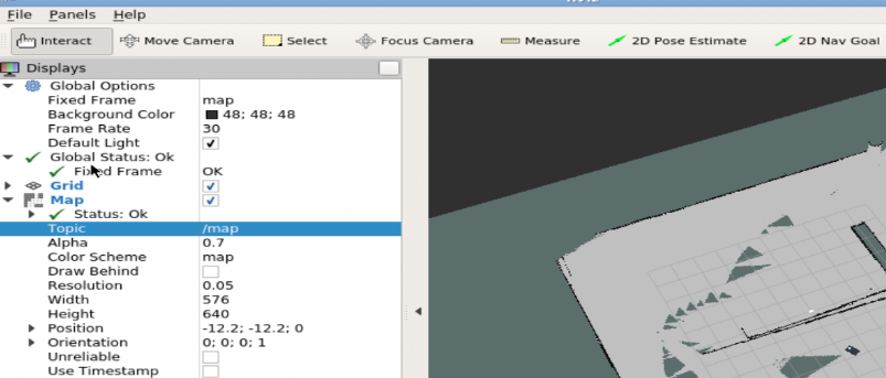
Open the graphical tools and configure RViz to show the robot model and the map being generated:

ROS GMapping RViz

One more shell.. Let’s use the teleop to drive the robot while it maps the environment:

rosrun teleop_twist_keyboard teleop_twist_keyboard.py

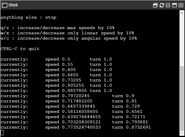
If you don’t know yet this package, this is used to send velocity commands to the robot using the keyboard. You can check the instructions on the shell itself:

ROS GMapping shell


Step 4 – Results

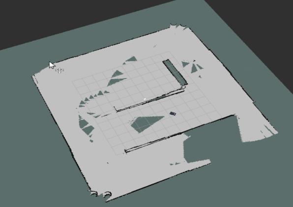
After driving the robot around the environment, you must have something similar to the image below:

ROS GMapping

The robot is placed more or less at the center of the world and we have almost the entire map generated.

It depends on the hardware, the odometry and the way you have navigated. But we have a map! Don’t we?!

Related Courses

ROS Navigation Course Cover - ROS Online Courses - Robot Ignite Academy

ROS Navigation

RTAB-Map Course Cover - ROS Online Courses - Robot Ignite Academy

RTAB-Map Course


Conclusion

After configuring the launch file, it’s quite easy to use gmapping. You can take advantage of this package to generate maps of different environments!

Don’t forget: If you have suggestions, doubts or just like this post, please, leave a comment and let us know your opinion.

See you!

Pin It on Pinterest