In questo tutorial vedremo come sia possibile configurare ROS per funzionare su più macchine connesse attraverso la rete, espandendo le possibilità per i tuoi progetti.
La configurazione iniziale parte da un nodo publisher minimale chatter.py appartenente al pacchetto chatter, con un singolo publisher di stringhe.
roscore
Consideriamo che un roscore per poter essere eseguito necessita di una configurazione iniziale di due variabili principali all’interno del nostro terminale (che sono inizializzate con un valore di default).
ROS_MASTER_URI Definisce l’indirizzo della macchina che avrà il ruolo di “master” per la nostra rete di ROS. La sua struttura è definita come
http://< indirizzo_della_macchina>:11311
ROS_HOSTNAME Definisce l’indirizzo della macchine ospite (quella che vogliamo che sia in grado di comunicare con il roscore), tipicamente l’ip della macchina che stiamo configurando.
Possiamo leggere il contenuto di queste due variabili con le seguenti istruzioni:
Come puoi vedere il nome dell’ospite e del master corrente è settato con un nome simbolico a causa dell’implementazione dei Rosject, nella tua macchina potresti vedere “localhost” o un indirizzo specifico se hai già modificato le variabili.
Ora, possiamo provare a runnare un roscore in un primo terminal, e a osservare il suo output.
roscore
# Output: process[master]: started with pid [4295]
# ROS_MASTER_URI=http://4_xterm:11311/
Possiamo notare quindi, come previsto, il ROS_MASTER_URI settato sulla macchina corrente.
Settare il roscore per connettere altre macchine
All’interno della macchina su cui vogliamo far girare il roscore e ospitare altre macchine (tipicamente la nostra macchina) dovremo cambiare i valori all’interno delle due variabili già menzionate.
All’interno della macchina che vogliamo utilizzare come ospite (tipicamente il nostro robot, o i nostri robot) dovremmo fare lo stesso, ma con valori differenti.
Vediamo quindi nel dettaglio come impostare questi valori.
Macchina ospitante
ROS_MASTER_URI dovrà essere impostato con l’ip della macchina all’interno della nostra rete. Per trovare questo ip si possono utilizzare le impostazioni di rete, del router, o anche comandi da terminale come ifconfig o ip addr. Poiché lavoreremo su un solo Rosject, utilizzeremo l’indirizzo corrispondente al localhost.
Assumiamo quindi che la nostra macchina abbia come indirizzo 127.0.0.1. In una prima shell eseguiamo:
exportROS_MASTER_URI=http://127.0.0.1:11311
exportROS_HOSTNAME=127.0.0.1
ROS_HOSTNAME sarà l’ip stesso della macchina.
Faremo lo stesso in una seconda shell, per scopo di testing.
Macchina ospite (e.g. robot)
ROS_MASTER_URI dovrà essere impostato con l’ip della macchina ospitante all’interno della nostra rete. Perciò utilizzeremo lo stesso comando della configurazione sulla macchina ospitante. In una terza shell, eseguiamo:
export ROS_MASTER_URI=http://127.0.0.1:11311
Per quanto riguarda ROS_HOSTNAME dovremo usare invece l’ip della macchina ospite, recuperabile con gli stessi metodi già menzionati. Assumiamo quindi che il nostro robot abbia come indirizzo ip 127.0.0.42.
export ROS_HOSTNAME=127.0.0.42
A questo punto le due macchine saranno in grado di comunicare e di avere accesso a tutti i messaggi pubblicati all’interno della rete e di pubblicare a loro volta.
Considerazioni importanti per questo rosject
Quando si cambiano i valori di queste variabili, la modifica sarà limitata alla shell su cui viene invocato il comando. Di fatto, aprendo una nuova shell, essa avrà nuovamente le variabili settate con i valori di default.
Sicuramente è possibile inserire i due comandi nel file ~/.bashrc, ma in questo caso non lo faremo per verificare l’effetto della modifica.
Test del nostro nodo
Nella terza shell (che sarebbe eseguita sul robot), possiamo quindi lanciare l’esecuzione del nostro nodo chatter (che possiamo interpretare come un nodo nel nostro robot che pubblica lo stato di un sensore).
rosrun chatter chatter.py
Grazie alla stampa ad output possiamo notare che il nodo inizia a inviare messaggi.
Andando quindi nella seconda shell (che si troverebbe sulla macchina del master) possiamo andare a stampare la lista dei topic pubblicati.
rostopic list
Ecco qui, anche se ci troviamo su una macchina differente, riceviamo i messaggi mandati dal nostro robot.
Osservazione
Se proviamo ad aprire una quarta shell, che quindi sarà configurata con i valori di default (a meno che le istruzioni di export non siano state messe nel file ~/.bashrc), questa shell non sarà in grado di interagire con il roscore, nemmeno se aperta sulla stessa macchina del master.
La configurazione dovrà essere ripetuta per ogni shell aperta, in accordo con la macchina su cui viene aperta (vedi differenze tra macchina ospitante e macchina ospite), oppure per comodità si potrà utilizzare il file ~/.bashrc.
Create a package for TurtleBot 3 to stop when an obstacle is detected
Introduction
In this tutorial, we’ll explore how to leverage Lidar data to implement a simple yet effective wall-avoidance mechanism for a robot, specifically the TurtleBot 3. By understanding the ‘ranges’ array from the laser scans, we can program our robot to make informed decisions and navigate around obstacles.
In this course, you’ll cover the foundational concepts needed to start working with ROS 2, as well as more advanced topics, all while engaging in hands-on practice.
Understanding LiDAR Data:
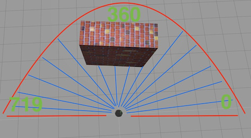
The Lidar sensor provides an array of values, with the middle values representing distances directly in front of the robot. Visualize the laser’s scope as approximately 180 degrees from right to left. Values at the array’s start and end correspond to side readings (left and right), while those in the middle relate to front readings. This spatial arrangement is crucial for determining the presence of a wall in the robot’s path.
Opening the rosject
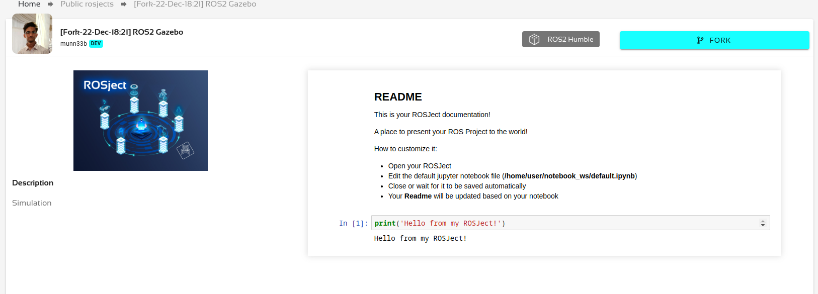
In order to follow this tutorial, we need to have ROS 2 installed in our system, and ideally a ros2_ws (ROS2 Workspace). To make your life easier, we have already prepared a rosject for that: https://app.theconstruct.ai/l/639b9a55/
Just by copying the rosject (clicking the link above), you will have a setup already prepared for you.
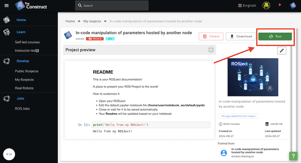
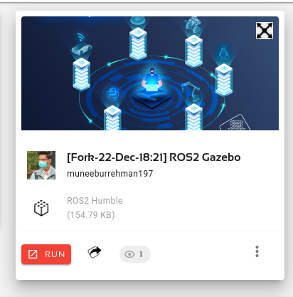
After the rosject has been successfully copied to your own area, you should see a Run button. Just click that button to launch the rosject.
After pressing the Run button, you should have the rosject loaded. Now, let’s head to the next section to get some real practice.
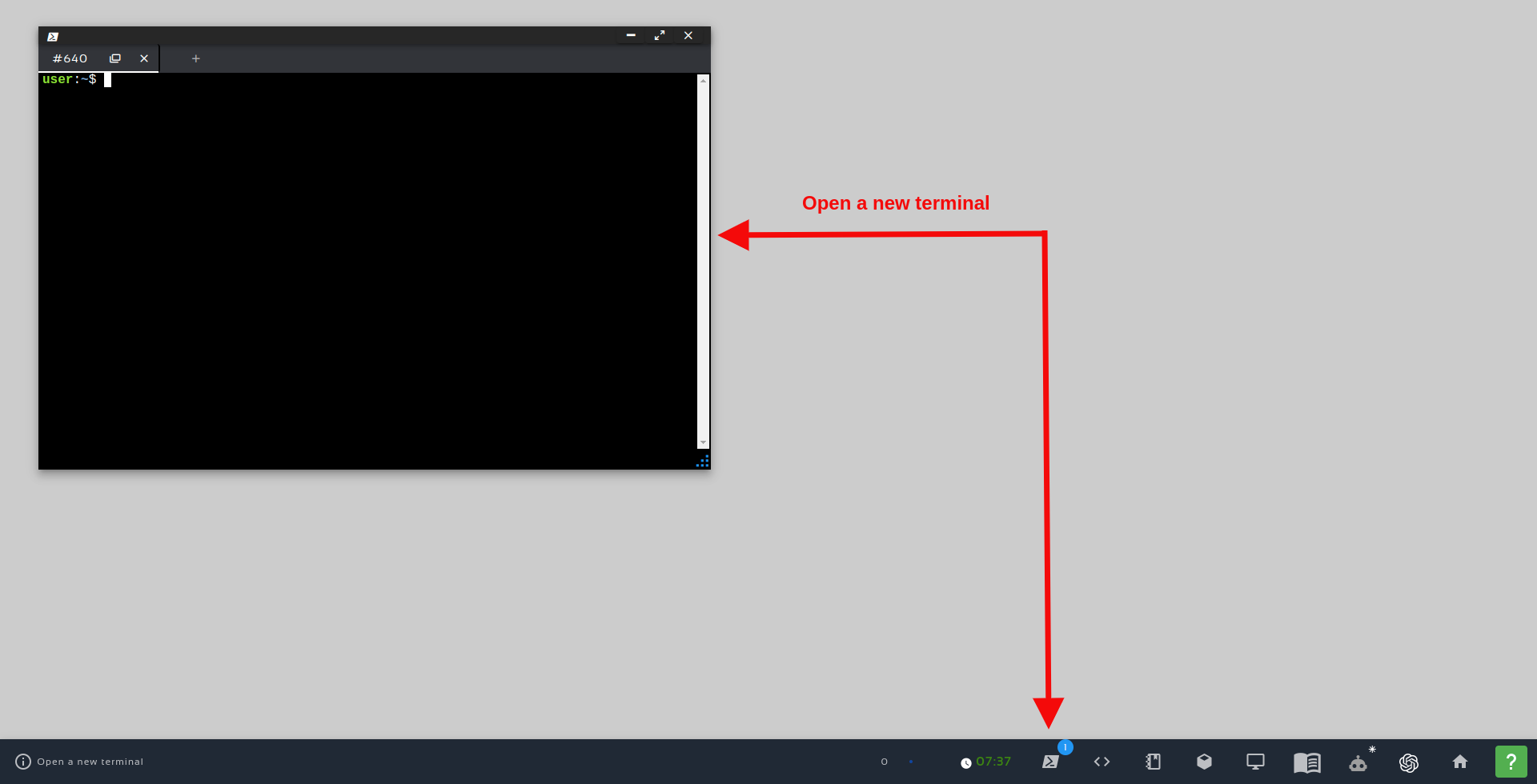
In order to interact with ROS2, we need a terminal.
Let’s open a terminal by clicking the Open a new terminal button.
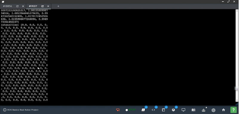
If we want to see data being published on /scan topic , we just have to write rostopic echo /scan
So for our application, we need the value of the array at the middle (index no 360).
Create a package for obstacle avoidance using lidar
Copy the rosject from the link attached at the starting of a tutorial as it already has TurtleBot package in it and write the below commands in web shell cd simulation_ws/src
catkin_create_pkg lidardata std_msgs rospy cd lidardata
mkdir launch mkdir src
cd launch
touch lidardata.launch cd ..
cd src
touch myscript.py chmod +x myscript.py cd
cd simulation_ws catkin_make
Logic of code
Let’s dive into the logic of our Python code. The goal is simple: if the distance directly in front of the robot is greater than 0.5 meters, it will continue moving forward; otherwise, it stops to avoid a collision. #! /usr/bin/env python
#Importing all the required Libraries and messages import rospy
from geometry_msgs.msg import Twist
from sensor_msgs.msg import LaserScan
# Create a Twist message to control robot movement
move_robot = Twist()
move_robot.linear.x = 0.5

move_robot.angular.z = 0

#Defining a call back function for the Subcriber. def callback(msg):

#Publish the movement command Pub1.publish(move_robot)

# Check distance directly in front of the robot (at the middle if(msg.ranges[360] > 0.5):

# If the distance is greater than 0.5 meters, move forward move_robot.linear.x = 0.1

move_robot.angular.z = 0.0

elif(msg.ranges[360] < 0.5):

# If the distance is less than 0.5 meters, stop to avoid collis move_robot.linear.x = 0.0

move_robot.angular.z = 0.0

# Initialize the ROS node rospy.init_node('lidar_data_node')

# Set up the robot movement publisher

Pub1 = rospy.Publisher('/cmd_vel',Twist,queue_size = 1)

# Set up the Lidar data subscriber

Sub1 = rospy.Subscriber('/scan',LaserScan,callback)

# Keep the node running and processing Lidar data rospy.spin()
Now we have created a node named ‘lidar_data_node’ which subscribes to topic ‘/scan’ and publishes velocity data to ‘/cmd_vel’.
How to create node in Python to spawn new object in Gazebo Simulation
Overview:
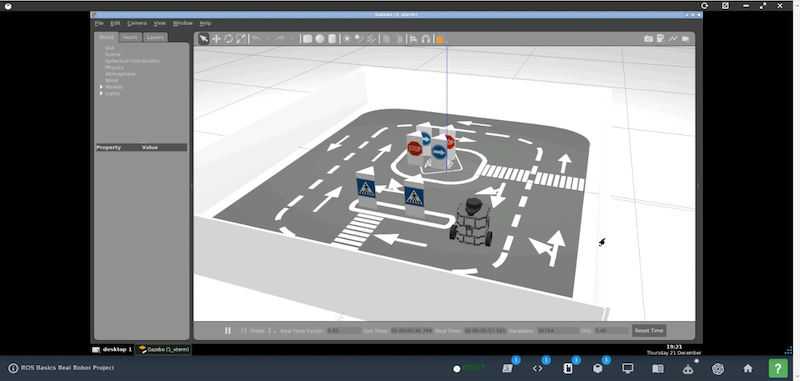
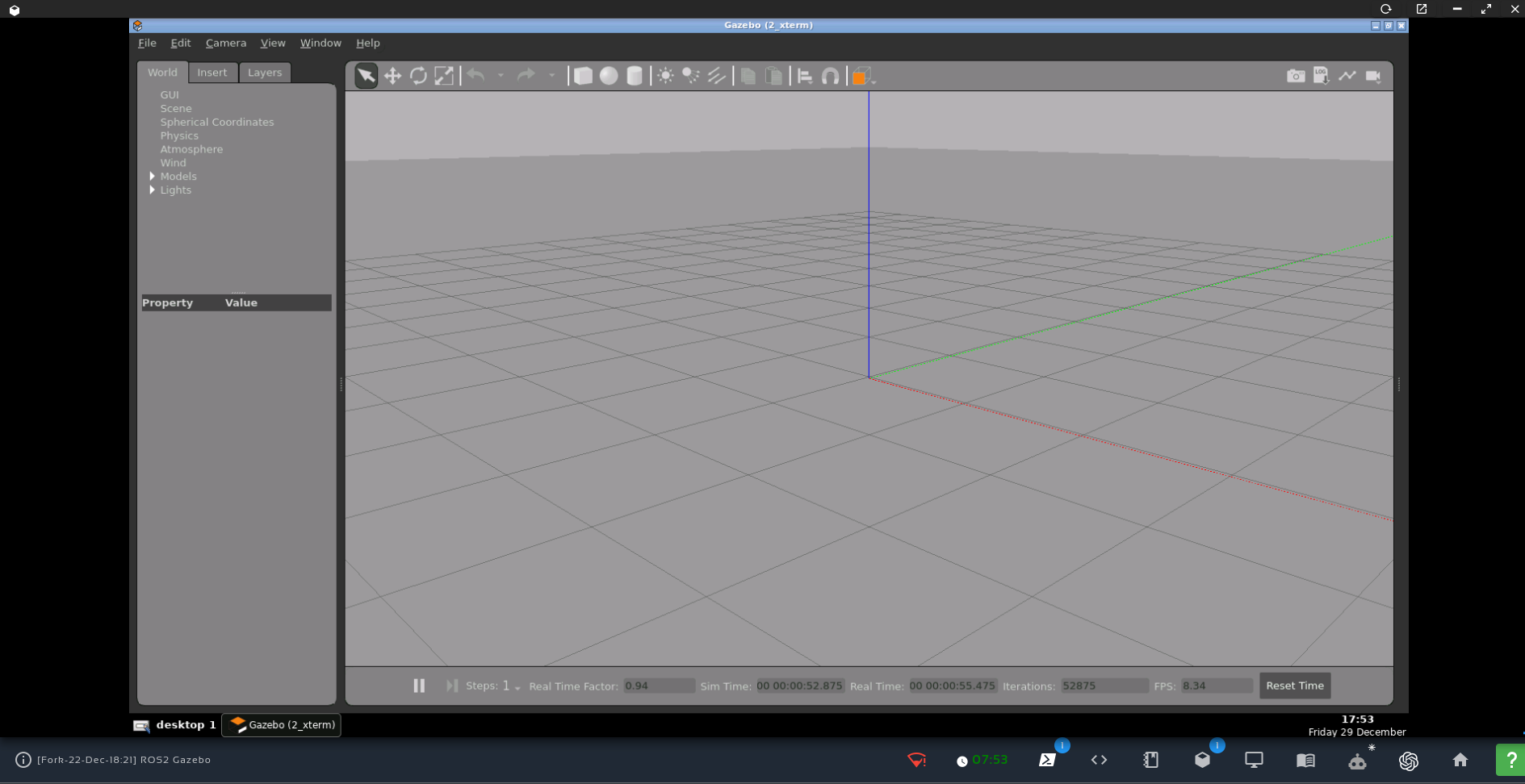
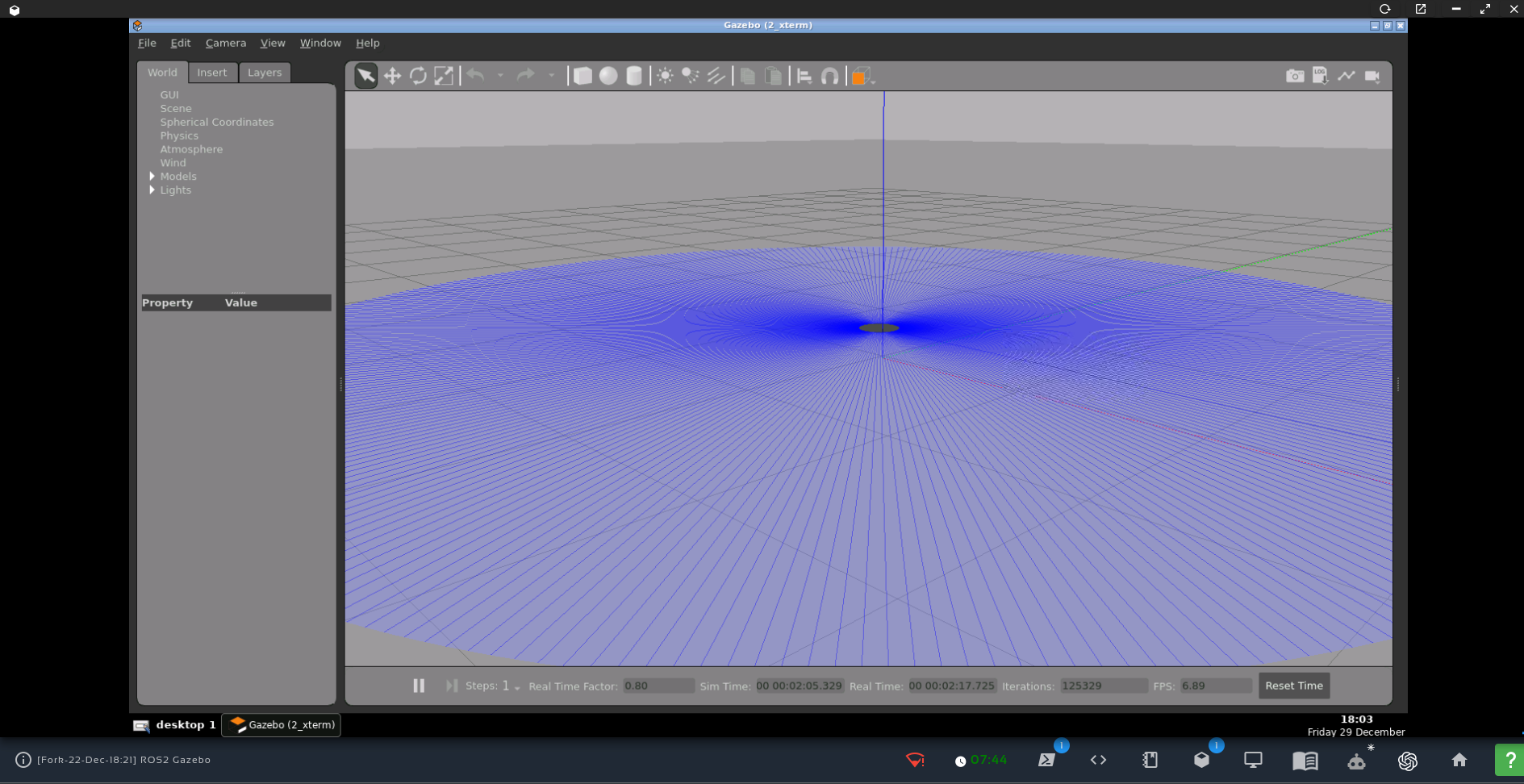
ROS (Robot Operating System) is a de facto standard for Robotics. In order to program Robots, simulation of Real world systems is very important to test and debug the systems. For simulations of Robotics systems, Gazebo is used commonly in ROS. In this post we will learn how to add new objects in simulation scene without terminating the simulation entirely.
In general, if we want to add new object in simulation scene, we have to terminate all running nodes in simulation, edit the World file (description file for simulation in Gazebo). In order to add new objects, without terminating nodes, we can use Gazebo API in Python to spawn new objects in simulation dynamically.
In this course, you’ll cover the foundational concepts needed to start working with ROS 2, as well as more advanced topics, all while engaging in hands-on practice.
ડી ફેક્ટો સ્ટાન્ડર્ડ “ફ્રેમવર્ક” બની રહ્યું છે . ROS2 માં ROS ફ્રેમ્સ દરેક જગ્યાએ છે અને તે શું છે અને તેનો ઉપયોગ કેવી રીતે કરવો તે સમજવું ખૂબ જ મહત્વપૂર્ણ છે.
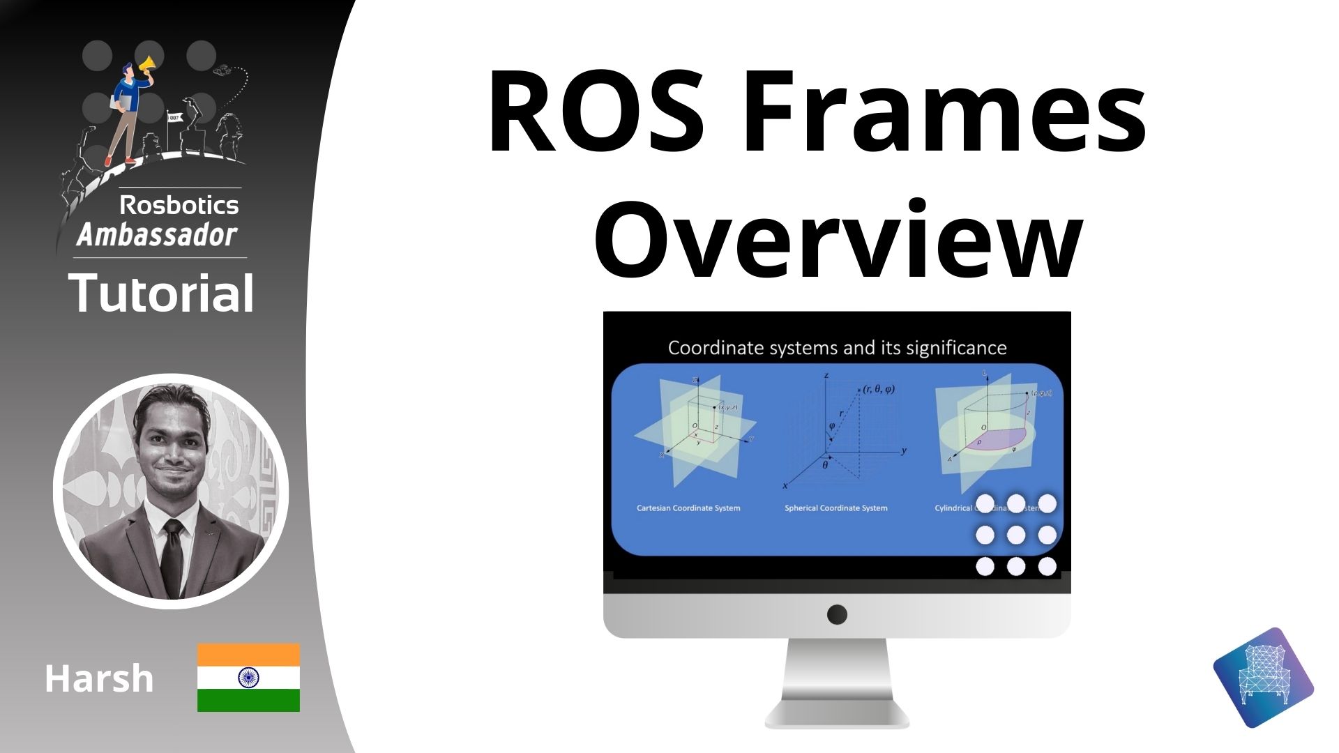
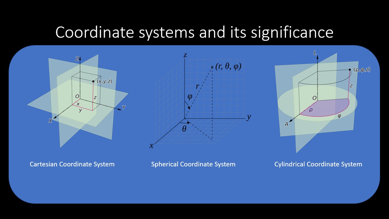
સંકલન પ્રણાલીઓ અને તેનું મહત્વ
ROS ફ્રેમ્સને ગાણિતિક સંદર્ભમાં કોઓર્ડિનેટ સિસ્ટમ્સ કહેવામાં આવે છે. કોઈપણ ગાણિતિક સમસ્યામાં જ્યાં આપણને રુચિના બહુવિધ ભૌમિતિક પદાર્થોની સ્થિતિ અથવા અભિગમને ઓળખવાની જરૂર હોય, ત્યારે આપણે સંદર્ભ પ્રણાલીને વ્યાખ્યાયિત કરવાની જરૂર છે. વિવિધ પરિમાણો અને ઉપયોગ-કેસો માટે રચાયેલ વિવિધ પ્રમાણભૂત સંકલન પ્રણાલીઓ છે જે જટિલ ગણતરીઓને સરળ બનાવવા અને બહુપરીમાણીય સિસ્ટમોને સમજવા, ડિઝાઇન કરવા અને તેનું પ્રતિનિધિત્વ કરવાનું અમારા માટે સરળ બનાવવા માટે ઘણી એપ્લિકેશનોમાં વ્યાપકપણે ઉપયોગમાં લેવાય છે. સામાન્ય અર્થમાં, સંકલન પ્રણાલીઓમાં બહુવિધ સ્વતંત્ર રેખીય સંદર્ભોનો સમાવેશ થાય છે જે સમાનરૂપે નાના એકમોમાં વિભાજિત થાય છે. આ અમારા માટે દરેક પરિમાણ સાથે સિસ્ટમમાં ઑબ્જેક્ટ્સ માટે સંભવિત સ્થિતિઓને અલગ પાડવાનું અને તેનું પ્રતિનિધિત્વ કરવાનું સરળ બનાવે છે.
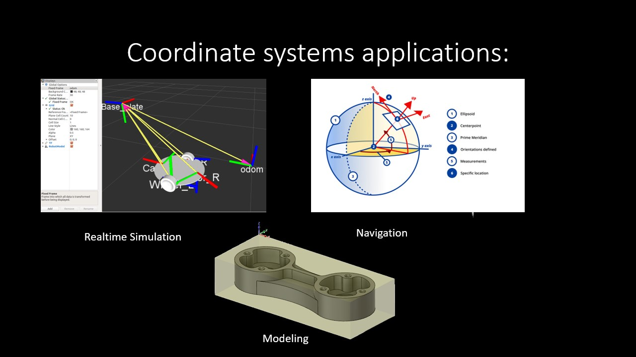
સંકલન પ્રણાલીના કેટલાક ઉદાહરણો ઉપર આપવામાં આવ્યા છે. સંદર્ભ તરીકે કોઓર્ડિનેટ સિસ્ટમનો ઉપયોગ કરીને અને કોઓર્ડિનેટ ભૂમિતિમાંથી ઉપલબ્ધ સાધનોનો ઉપયોગ કરીને, વાસ્તવિક સમયના સચોટ સિમ્યુલેશન, મોડેલિંગ અને નેવિગેશન જેવી જટિલ ગણતરીઓ વિકસાવવી સરળ બની છે.
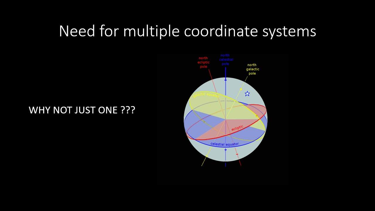
બહુવિધ સંકલન પ્રણાલીઓની જરૂર છે
હવે જ્યારે આપણે કોઓર્ડિનેટ સિસ્ટમ્સ સમજીએ છીએ, ત્યારે આપણે સમજવાની જરૂર છે કે શા માટે આપણને કોઈપણ એપ્લિકેશનમાં બહુવિધ કોઓર્ડિનેટ સિસ્ટમ્સની જરૂર પડશે? શા માટે માત્ર એક જ સંકલન પ્રણાલી સાથે કામ ન કરવું?
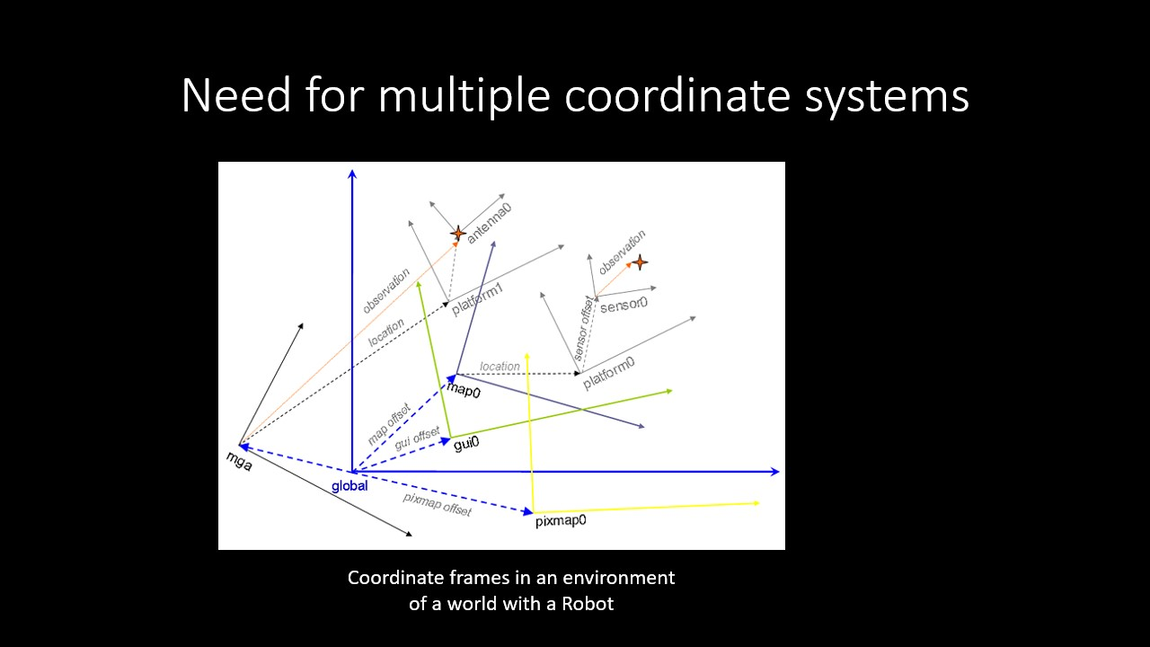
સૌથી સરળ જવાબ એ છે કે બ્રહ્માંડ ખરેખર એક વિશાળ પર્યાવરણ છે, અને અમે કોઈપણ એપ્લિકેશન માટે ક્યારેય એક એકીકૃત સંકલન પ્રણાલીને વ્યાખ્યાયિત કરી શકીશું નહીં. સંકલન પ્રણાલીનો ઉપયોગ કરવાનો મુખ્ય મુદ્દો એ છે કે મૂળ અને અક્ષ ક્યાં હશે તે પસંદ કરવાની ક્ષમતા. વિવિધ એપ્લિકેશનો માટે સમાન સિસ્ટમમાં વિવિધ સંકલન સિસ્ટમો હોઈ શકે છે. સિસ્ટમમાં સબસિસ્ટમ્સ પણ હોઈ શકે છે જેની પોતાની કોઓર્ડિનેટ સિસ્ટમ હોય છે. સિસ્ટમની અંદર સમગ્ર સબસિસ્ટમ વંશવેલો હોઈ શકે છે. ઓટોમોબાઈલ ડિઝાઇન, રોબોટિક્સ મેનીપ્યુલેશન અથવા તો ગેમિંગ સિસ્ટમ્સ જેવી ખૂબ જ જટિલ એપ્લિકેશનો માટે, તે અમને સમગ્ર સિસ્ટમને નાના ઘટકોમાં વિભાજીત કરવાની અને સંબંધિત કાર્યોને સરળ વિગતવાર રીતે કરવાની ક્ષમતા આપે છે જેથી તેના આધારે વર્કફ્લોને વિભાજિત કરવાનું સરળ બને. ઘટકો, તેમને જાળવી રાખે છે અને તેમના રાજ્યોને નિયંત્રિત પણ કરે છે.
ઘણી બધી ફ્રેમ્સ! હું તેમની સાથે કેવી રીતે કામ કરી શકું?
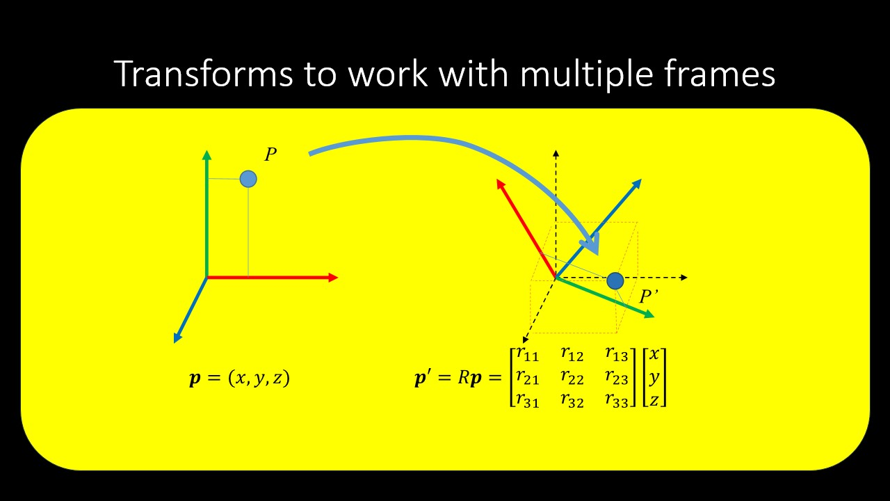
હવે આપણને બહુવિધ કોઓર્ડિનેટ ફ્રેમ્સની જરૂરિયાતનો ખ્યાલ છે, આપણે આ બધી વિવિધ કોઓર્ડિનેટ ફ્રેમ્સ સાથે કેવી રીતે કામ કરીશું. બીજાના સંદર્ભમાં સંકલન ફ્રેમનું પ્રતિનિધિત્વ કરવા માટે આપણને અન્ય સંબંધમાં ફ્રેમની સંબંધિત સ્થિતિ અને અભિગમની જરૂર છે. આ બંનેને સમાવિષ્ટ કરવાથી આપણે જેને રૂપાંતર કહીએ છીએ તે મેળવીએ છીએ.
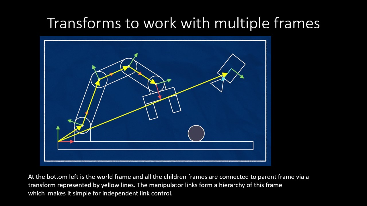
ગાણિતિક રીતે રૂપાંતરણને રજૂ કરવા અથવા તેનો ઉપયોગ કરવાની વિવિધ રીતો છે. સ્ટાન્ડર્ડ એ વર્લ્ડ કોઓર્ડિનેટ ફ્રેમને વ્યાખ્યાયિત કરવાનું છે અને દરેક કોઓર્ડિનેટ ફ્રેમના રૂપાંતરણોને સંગ્રહિત કરવાનું છે જેનો આપણે વિશ્વ ફ્રેમ અનુસાર ઉપયોગ કરવાની જરૂર છે. જટિલ સિસ્ટમોને સરળ બનાવવા માટે, અમે આ સબસિસ્ટમ્સની વંશવેલો બનાવીએ છીએ જ્યાં અમે પેરેંટ ફ્રેમના સંદર્ભમાં ચાઇલ્ડ ફ્રેમના ટ્રાન્સફોર્મને સંગ્રહિત કરીએ છીએ જેથી માતાપિતાની સ્થિતિ બદલાય તો સંદર્ભ સાથે કામ કરવું અને વિશ્વના સંદર્ભમાં ઑબ્જેક્ટનું સ્થાનિકીકરણ કરવું વધુ સરળ છે.
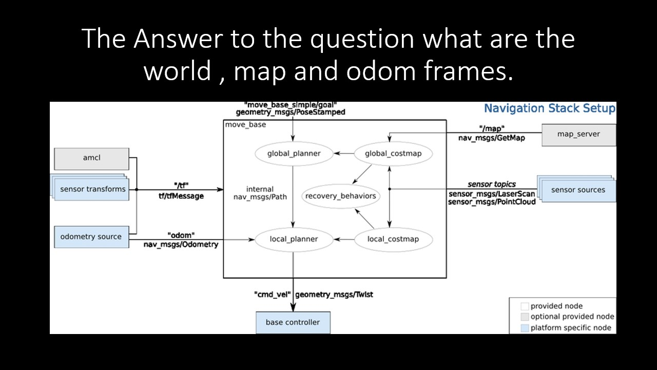
/world, /map અને /odom ફ્રેમ્સ શું છે?
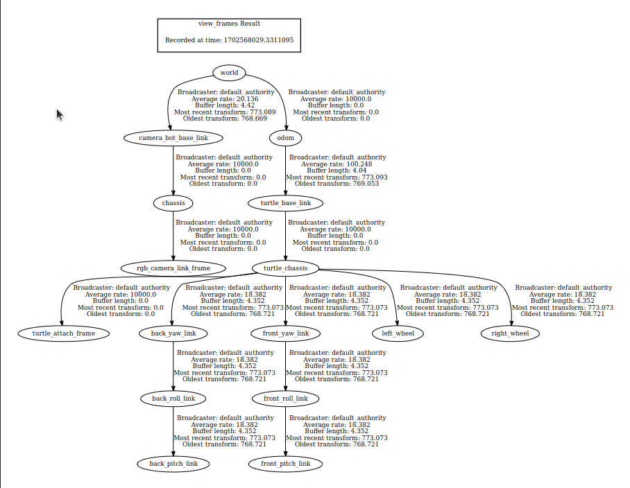
તમે ઉપર જે જુઓ છો તે પ્રમાણભૂત ROS નેવિગેશન સ્ટેકના ઘટકો છે. મેપિંગ, સ્થાનિકીકરણ અને ઓડોમેટ્રી એ એવા ઘટકો છે જે આપણને એ સમજવામાં મદદ કરે છે કે રોબોટ વિશ્વમાં ક્યાં છે.
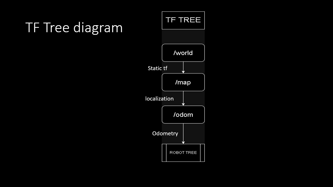
અહીં સિમ્યુલેટેડ રોબોટનું TF વૃક્ષ છે. રોબોટના આધારની ફ્રેમ “/base_link” છે. ઉલ્લેખ કર્યો છે તેમ, ફ્રેમનો વંશવેલો ક્રમ /world, /map, /odom અને /base_link છે. આ ત્રણ એવી કેટલીક ફ્રેમ્સ છે જે ફ્રેમ્સ હાયરાર્કી (ROS TF TREE) માં હાજર રહેવાની અપેક્ષા છે.
/ વર્લ્ડ ફ્રેમ સુપર પેરેન્ટ છે, જે TF વૃક્ષના મૂળમાં સ્થિત છે. અમે જે અન્ય ફ્રેમ પર કામ કરીએ છીએ તે બાળકો અથવા વિશ્વના દૂરના બાળકો છે.
/ મેપ ફ્રેમ નકશા સર્વર દ્વારા બનાવવામાં આવે છે જે પર્યાવરણની સંકલન પ્રણાલીને વ્યાખ્યાયિત કરે છે જ્યાં રોબોટ ખસેડી શકે છે. વિશ્વ ફ્રેમના સંદર્ભમાં આ એક સ્થિર સંકલન ફ્રેમ છે. આ ફ્રેમ “નકશા_સર્વર” દ્વારા લોડ કરવામાં આવી છે. આ ફ્રેમની ઉત્પત્તિ મેપિંગની પ્રક્રિયા પર આધારિત છે.
/odom ફ્રેમ એ ફ્રેમ છે જ્યાં રોબોટ તેની નેવિગેશન ફ્રેમ શરૂ કરે છે. નકશાથી ઓડોમ ટ્રાન્સફોર્મની ગણતરી કરવાની પ્રક્રિયાને સ્થાનિકીકરણ કહેવામાં આવે છે. ઓડોમ થી બેઝ_લિંક ટ્રાન્સફોર્મની ગણતરી કરવાની પ્રક્રિયાને ઓડોમેટ્રી કહેવામાં આવે છે.
ઓડોમેટ્રી અને સ્થાનિકીકરણ માટે વિવિધ પ્લગઇન્સ અને અલ્ગોરિધમ્સ ઉપલબ્ધ છે. નેવિગેશન કોર્સમાં વિગતવાર માહિતી ઉપલબ્ધ છે.
tf સાથે મૂળભૂત કામગીરી
ROS2 માંથી ઉપલબ્ધ સાધનોનો ઉપયોગ કરીને tf સાથે કરવા માટે અહીં કેટલીક મૂળભૂત કામગીરી છે. આ વિભાગ ધારે છે કે તમારી પાસે સાધનો સાથે સુલભ પ્લેટફોર્મ સેટઅપ છે. વધુ વિગતો માટે ROS2 tf કોર્સનો સંદર્ભ લો.
પીડીએફ ફોર્મેટમાં ફ્રેમ જુઓ
ફ્રેમ્સ જોવા માટે , ROS2 નોડ સિસ્ટમના વર્તમાન TF ટ્રી સાથે ડાયાગ્રામ બનાવે છે.
નીચેનો આદેશ ડિરેક્ટરીમાં પીડીએફ ફાઇલ બનાવે છે જ્યાં તે ચલાવવામાં આવે છે:
તમારી પાસે હવે ફ્રેમ્સ_XXXXXX.pdf નામની PDF ફાઇલ હોવી જોઈએ જેમાં વર્તમાન TF ટ્રી છે જે હાલમાં સિસ્ટમમાં બ્રોડકાસ્ટ થઈ રહ્યું છે, જ્યાં XXX એ તારીખ છે જ્યારે ફાઇલ જનરેટ કરવામાં આવી હતી.
ઉદાહરણ પીડીએફ:
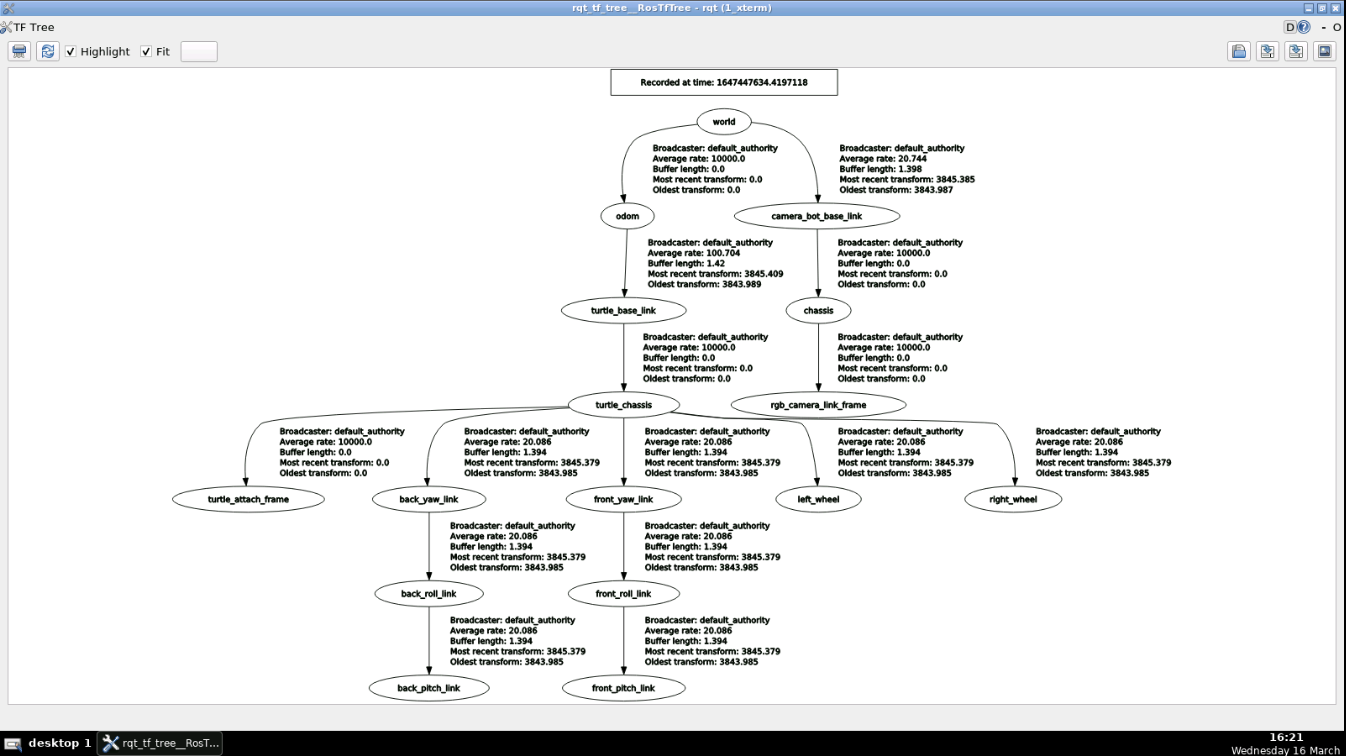
rqt_tf_tree નો ઉપયોગ કરીને TF ફ્રેમ્સ જુઓ
rqt_tf_tree એ view_frames જેવી જ કાર્યક્ષમતા આપે છે , પરંતુ તમે દર વખતે બીજી PDF ફાઈલ જનરેટ કર્યા વિના તાજું કરી શકો છો અને ફેરફારો જોઈ શકો છો .નવા TF બ્રોડકાસ્ટનું પરીક્ષણ કરતી વખતે અને તમે જે ઉપયોગ કરી રહ્યાં છો તે હજુ પણ પ્રકાશિત થયેલ છે અથવા જો તે જૂનું પ્રકાશન છે કે કેમ તે તપાસતી વખતે આ ઉપયોગી છે.
ros2 run rqt_tf_tree rqt_tf_tree
ઉદાહરણ આઉટપુટ:
હવે, આ TF સ્થિર નથી, પરંતુ TF વૃક્ષની વર્તમાન સ્થિતિ દર્શાવવા માટે તેને તાજું કરી શકાય છે. જ્યારે પણ તમે નવીનતમ અપડેટ ઇચ્છો ત્યારે રિફ્રેશ બટન દબાવો.
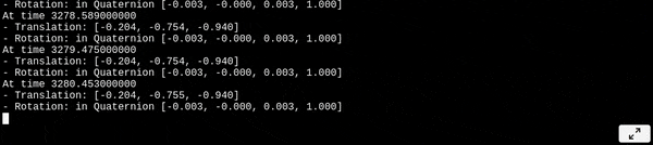
tf_echo નો ઉપયોગ કરીને ટર્મિનલમાં TF ફ્રેમ્સ જુઓ
નીચે, આરઓએસ રૂપાંતરણોને સંચાર કરવા માટે વિષયોનો ઉપયોગ કરે છે. પરિણામે, તમે વિષયો દ્વારા આ તમામ કાચો ડેટા જોઈ શકો છો. ત્યાં /tf નામનો વિષય છે અને અન્ય નામનો /tf_static છે, જ્યાં તમામ TF પ્રકાશિત થાય છે. એકમાત્ર સમસ્યા એ છે કે તમામ ફ્રેમ્સ ત્યાં પ્રકાશિત થાય છે. ત્યાં એક સરળ કમાન્ડ લાઇન ટૂલ છે જે ફિલ્ટર કરે છે કે જે પરિવર્તનમાં તમને રસ છે અને તમને તે બતાવે છે. અથવા, વધુ અગત્યનું, તે બે કનેક્ટેડ ફ્રેમ્સ વચ્ચેના પરોક્ષ રૂપાંતરણની ગણતરી કરે છે, પરંતુ સીધી રીતે નહીં. આ ઉપયોગી છે અને ઘણી એપ્લિકેશનો માટે વપરાય છે. /tf વિષય ફક્ત ડાયરેક્ટ TF પ્રકાશિત કરે છે, બધી ફ્રેમ્સ વચ્ચેના તમામ રૂપાંતરણોને નહીં. tf_echo તમને કોઈપણ કનેક્ટેડ ફ્રેમ્સ વચ્ચેના રૂપાંતરણ પરત કરે છે.
/tf વિષયનું એક પ્રકાશન સીધું જોવા માટે નીચેનો આદેશ ચલાવો:
ros2 topic echo /tf
અમે મોટા ભાગના કિસ્સાઓમાં ફ્રેમ્સ વચ્ચેના પરિવર્તન વિશે જાણવામાં રસ ધરાવીએ છીએ, ઉદાહરણ તરીકે રોબોટનું સ્થાન શું છે તે જાણવું અથવા તેના માતાપિતાના સંદર્ભમાં રોબોટના હાથની લિંક્સમાંથી કોઈ એકનું ઓરિએન્ટેશન/પોઝિશન શું છે. આનો અર્થ એ છે કે તમે reference_frame થી target_frameમાં અનુવાદ અને પરિભ્રમણ જાણવા માગો છો . tf2_echo આદેશ નીચેની સામાન્ય રચના સાથે ચલાવવાનો છે:
ros2 run tf2_ros tf2_echo [reference_frame] [target_frame]
ઉદાહરણ આઉટપુટ:
સંદર્ભોમાં વધુ વિગતવાર સમજૂતી ઉપલબ્ધ છે.
સંબંધિત અભ્યાસક્રમો અને તાલીમ
જો તમે ROS અને ROS2 વિશે વધુ જાણવા માંગતા હો, તો અમે નીચેના અભ્યાસક્રમોની ભલામણ કરીએ છીએ:
ROS (Robot Operating System) se está convirtiendo en el “framework” estándar para programar robots. En esta publicación, aprenderemos a usar adecuadamente Robot State Publisher para publicar las transformaciones TF de los sistemas coordenados de nuestro robot. Así como, lo necesario para visualizar el robot en RViz y Gazebo.
Abriendo el rosject
Para seguir este tutorial, necesitamos tener instalado ROS en nuestro sistema, y lo ideal sería tener un catkin_ws (Espacio de Trabajo ROS). Para facilitarte la vida, ya hemos preparado un rosject para eso: https://app.theconstructsim.com/l/5e2843be/.
Simplemente copiando el rosject (haciendo clic en el enlace de arriba), tendrás una configuración ya preparada para ti.
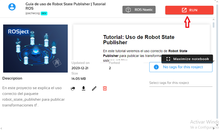
Después de haber copiado el rosject a tu propia área de trabajo, deberías ver el botón RUN. Haz clic en ese botón para lanzar el rosject (abajo tienes un ejemplo de rosject).
Tras pulsar el botón RUN, deberías tener cargado el rosject. Ahora, pasemos a la siguiente sección para ponernos manos a la obra.
Iniciando Robot State Publisher y visualizando el robot en RViz
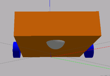
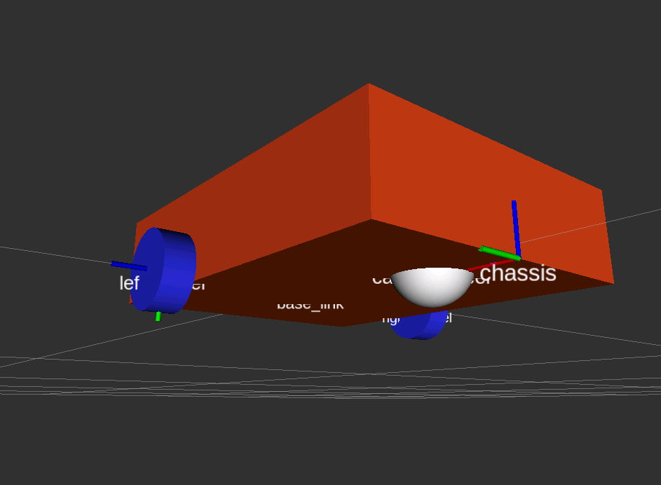
Para usar Robot State Publisher necesitamos de la descripción de un robot en archivos urdf o xacro. En este rosject usaremos archivos xacro de un robot móvil simple, los cuales están en la carpeta robot de nuestro paquete robot_tutorial.
Robot a usar en el tutorial – mobile_robot
Creamos un archivo launch robot_visualization.launch para iniciar robot_state_publisher. Para ello, en un nuevo terminal colocamos lo siguiente: cd /home/user/catkin_ws/src/robot_tutorial
mkdir launch
touch launch/robot_visualization.launch
En ese archivo creado colocamos:
robot_visualization.launch <launch>
<!-- Cargar el URDF en el servidor de parámetros de ROS -->
<param name="robot_description" command="$(find xacro)/xacro $(find robot_tutorial)/robot/mobile_robot.urdf.xacro" />
<!-- Iniciamos robot_state_publisher para publicar las tranformaciones tf -->
<node name="robot_state_publisher" pkg="robot_state_publisher" type="robot_state_publisher"
output="screen">
<param name="publish_frequency" type="double" value="5.0" />
</node>
</launch>
Con esto:
Cargamos la descripción del robot en el parámetro robot_description.
Iniciamos el nodo robot_state_publisher que tomará la descripción del robot para publicar las transformaciones con una frecuencia de 5Hz.
Previamente, antes de iniciar el launch nos aseguramos de compilar nuestro paquete, para ello, en un terminal colocamos:
cd /home/user/catkin_ws

catkin_make

source devel/setup.bash

rospack profile
Con ello, ya podemos iniciar nuestro archivo launch: roslaunch robot_tutorial robot_visualization.launch
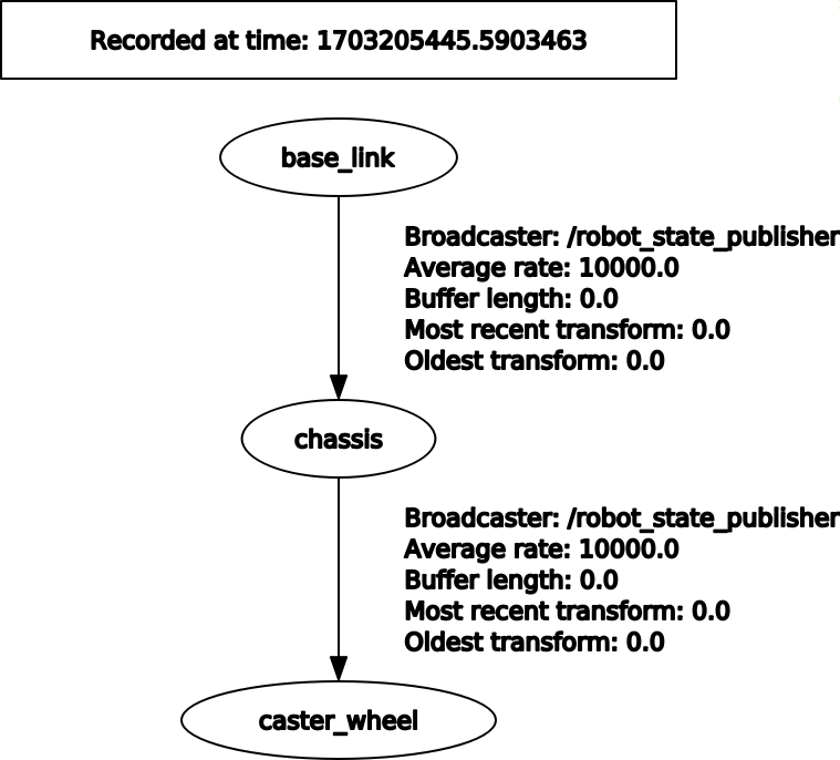
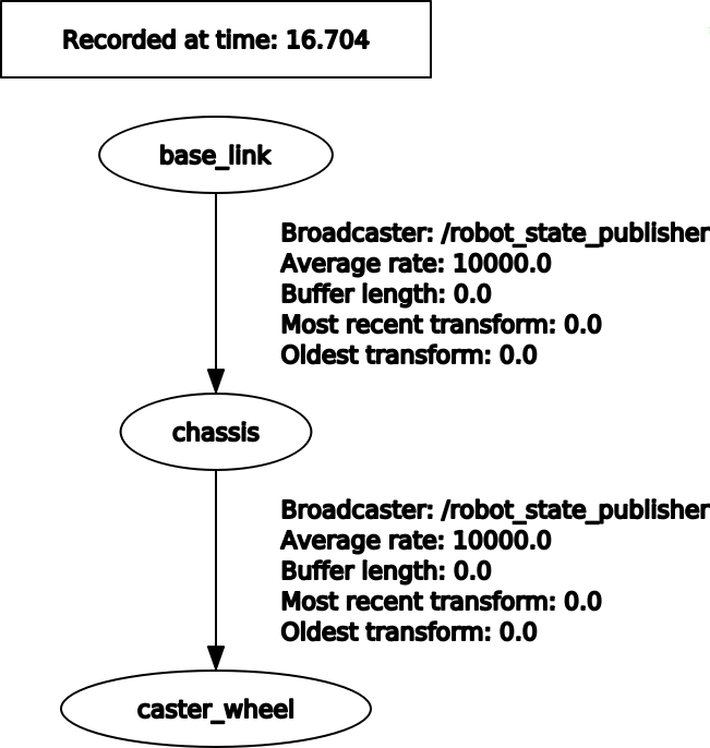
Al iniciar el launch y visualizar el árbol TF usando rosrun rqt_tf_tree rqt_tf_tree obtenemos que no están presentes las transformaciones de las juntas no fijas, es decir, de las ruedas.
Árbol de tf publicado por robot_state_publisher – incompleto
Esto se debe a que robot_state_publisher necesita que se publiquen los valores de las juntas no fijas para hacer las transformaciones, de lo contrario solo publicará las trasformaciones estáticas (juntas fijas).
Por ello debemos añadir un nodo que publique los valores de las juntas de alguna manera. Usaremos para ello joint_state_publisher_gui. Añadimos lo siguiente al archivo recién creado:
Iniciamos el nodo joint_state_publisher_gui para que publique los valores de las juntas de las ruedas.
Iniciamos RViz con una configuración que guardaremos en launch/robot.rviz
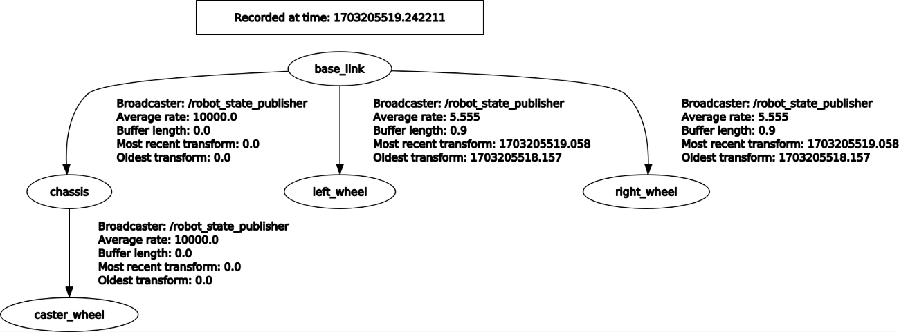
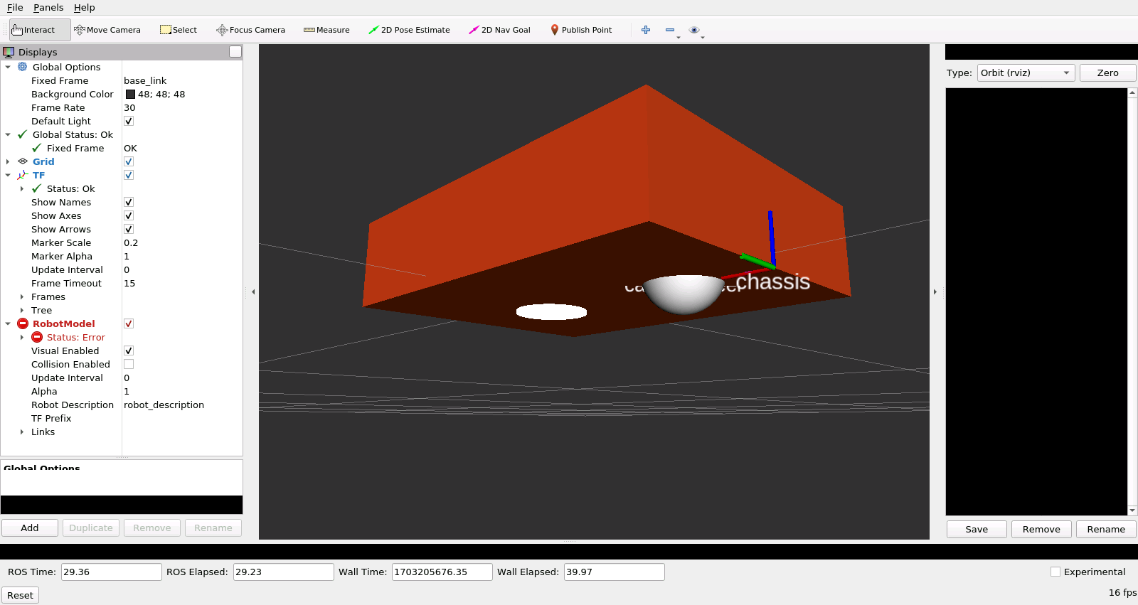
Con ello ya vemos las transformaciones faltantes al usar rqt_tf_tree y también podemos ver el robot en RViz.
Árbol de tf publicado por robot_state_publisher – completo
Robot en RViz – completo
cd /home/user/catkin_ws/src/robot_tutorial

mkdir config

touch config/robot_control.yaml
En este archivo nuevo, colocaremos el controlador joint_state_controller, que será el encargado de publicar los valores de las juntas no fijas del robot simulado en Gazebo.
robot_control.yaml
# Publicar todos los estados de las juntas (/joint_states) -----------------------------------

joint_state_controller:

type: joint_state_controller/JointStateController

publish_rate: 50
Posteriormente, creamos otro archivo launch donde colocaremos lo necesario para la simulación. cd /home/user/catkin_ws/src/robot_tutorial
touch launch/spawn_robot.launch
En este archivo, colocamos lo siguiente: <launch>
<arg name="x" default="0.0" />
<arg name="y" default="0.0" />
<arg name="z" default="0.2" />
<arg name="robot_name" default="mobile_robot" />
<!-- Cargar el URDF en el servidor de parámetros de ROS -->
<param name="robot_description" command="$(find xacro)/xacro $(find robot_tutorial)/robot/mobile_robot.urdf.xacro" />
Establecer una posición de aparición del robot en el mundo de Gazebo.
Asignamos un nombre al robot (mobile_robot).
Cargar la descripción del robot en el parámetro robot_description.
Cargamos el controlador joint_state_controller que definimos previamente.
Iniciar el nodo robot_state_publisher con una frecuencia de publicación de 5Hz.
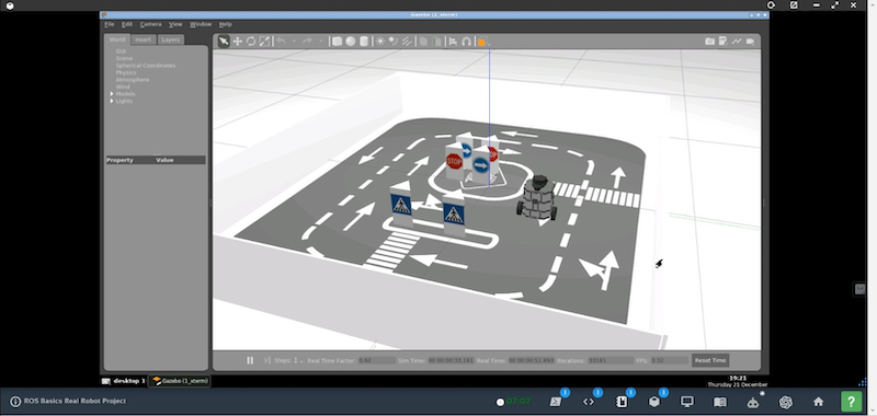
Iniciamos un mundo vacío en Gazebo.
Iniciamos el controlador usando el nodo controller_spawner.
Hacemos aparecer el robot en el mundo de Gazebo usando el nodo urdf_spawner pasándole los parámetros de posición, nombre y descripción del robot que previamente definimos.
Iniciamos RViz con la configuración que ya guardamos en launch/robot.rviz
Iniciamos este launch con: roslaunch robot_tutorial spawn_robot.launch
Al iniciar el launch y visualizar el árbol TF usando rosrun rqt_tf_tree rqt_tf_tree observamos el mismo problema anterior, esto se debe a que, para gazebo, es necesario colocar las transmisiones a todas las juntas no fijas al final del archivo xacro de nuestro robot.
Árbol de tf publicado por robot_state_publisher – incompleto
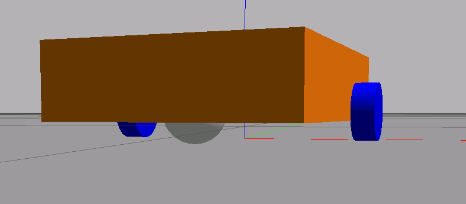
Robot en RViz – incompleto
Para ello nos dirigimos al archivo xacro principal de nuestro robot para añadir en la parte final lo siguiente:
Añadimos la transmisión a la junta left_wheel_joint (debe ser el mismo nombre de la junta usada en la definición del joint).
Añadimos la transmisión a la junta right_wheel_joint (debe ser el mismo nombre de la junta usada en la definición del joint).
Con ello ya se visualizan las transformaciones de todas las juntas del robot y ya tenemos el robot tanto en RVIZ como en Gazebo listo para añadir los controladores y sensores que se requieran.