In this video, we are answering a question about why the range sensor plugin for Gazebo is not detecting obstacles. The answer to that problem will surprise you !!! (ha, ha, ha).
In this posting, we will go through a demo of laser data visualization
NOTE: This article assumes that the audience is familiar with the following:
Running scripts on the terminal
Ros filesystem layout (what goes where launch dir, src dir etc)
RDS Environment (How to launch a project, how to navigate the directories.
Step – 3. Briefly skim through the code and run it
First, we go through the contents of package.xml (located inside the fakeLaserScan directory) which has the following content
(NOTE comments are removed in this reproduced code snippet for brevity)
This file contains various pieces of information about the project such as the package dependencies (roscpp, rospy, sensor_msgs, std_msgs) project name, version, license, maintainer etc. Some of this information is vital for building the project (like the dependencies). While other information is important from the perspective of sharing one’s work with the community.
In the given contents of the package.xml file, we notice that the project name specified in the file (beginner_tutorials) is different from the directory name (fakeLaserScanner). While this will not cause the project to crash but it is inconsistent with the project naming guideline.
Next, we take a look at the code inside fakeLaserScan.cpp
This code creates a publisher with the name fakeScan
The scan values are being generated inside a for loop (line 15-18 (excluding the blank lines))
These scan values are then copied to a LaserScan message (line 20, 32-35)
The message is being published at line 36. Also, note that the publish rate is 1 Hz (line 12)
As all seems okay we will go ahead and build the project. On the console browse to the catkin_ws directory and then run
$ catkin_make
This should proceed without any errors.
Next, we launch the project with the following command
$ roslaunch beginner_project fakeLaserScan.launch
This also should proceed without any errors.
Now we will open another console from the Tools menu and verify the topics with following commands
$ rostopic list
Outputs :
/fakeScan
/rosout
/rosout_agg
In the result, we see out topic /fakeScan appears. Further, we can check if the topic is publishing the correct information or not with the following command
Let’s try this out and solve this problem in ROS Development Studio. You can register a free account and follow the tutorial below!
Step1: create a package
After creating a new project in RDS, open a new shell from the tools tab and type the following command into the shell to create a ROS package.
cd catkin_ws/src/
catkin_create_pkg video_qa rospy
Step2: create a test file for the code.
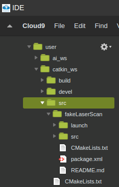
It’s easier to do this with an IDE. You can find IDE in the tools tab.
Now right click and select the new file to open a new file testunder the folder /video_qa/src
Paste the following code into the test file.
#! /usr/bin/env python

import rospy

rospy.init_node('test')
rate = rospy.Rate(1)

while not rospy.is_shutdown():
    print "Hello there"
    rate.sleep()
Step3: create a launch file
According to ROS’s file structure, the launch file should be created under the launch directory. Let’s create it with the IDE and add a test.launch file under the /video_qa/launch folder.
To run the code with roslaunch, we need to start roscore. You can either do that by typing roscore into the shell or start a simulation from the Simulations tab.
Step5: rosrun and roslaunch
Firstly, we try to directly execute the test file using rosrun video_qa test, but we got some error message.
[rosrun] Couldn’t find executable named test below /home/user/catkin_ws/src/video_qa
…
That’s because of the lack of permission for this file. We can give the file permission by typing:
chmod +x video_qa/src/test
then we do rosrun video_qa test again. It works!
Then we try roslaunch video_qa test.launch. Strangely, it also works…WHY?
It turns out if we name the file test.py instead of test, we will have the same problem. To solve it, we rename the file to test.py and also in the launch file we use test.py instead of test.
TAKEAWAY:
Always name the file with extension(e.g. test.py). However, the type in the launch file takes the executable during the compiling process. Since there is no need for compiling .py file. If you use python, just put the file name with the extension(e.g. test.py) in the type section.
I hope you enjoy the ROS Q&A video today. If you are interested in learning ROS, please check the links below for the Robot ignite academy.
In this video, we are going to answer a question found at ROS answers (https://goo.gl/ws2Whw). The person is asking why he cannot show the laser data of a fake laser given that he is publishing the proper frame and even a static transform from the laser to map. Very simple and surprise answer!
Step 1. Create project
Instead of installing and configuring a ROS environment locally, we can easily reproduce this question in ROS Development Studio. You can register an account for free now! After signing up and creating a new project, we can clone the repo provided in the question into the workspace. Open a Shell window in the Tools tab and type the following command:
Step 3. Check if the topic is publishing correctly
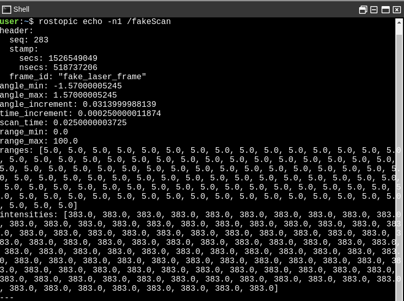
To check if the node we just launched really publishing something, we open another shell and type
$ rostopic echo -n1 /fakeScan
The fakeScan topic is publishing.
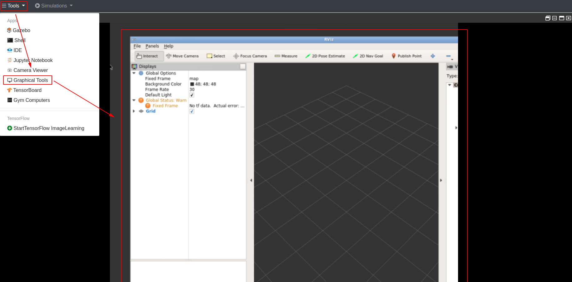
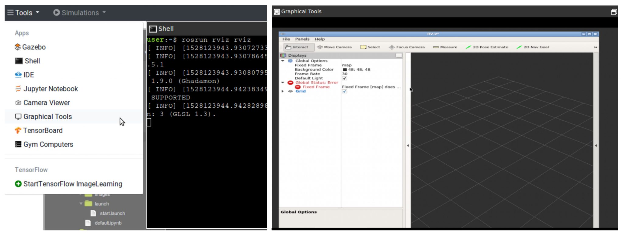
Let’s check it further with Rviz by typing.
$ rosrun rviz rviz
1.In order to see Rviz running in the RDS, open the Graphical Tools in the Tools Tab.
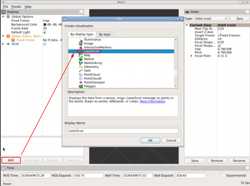
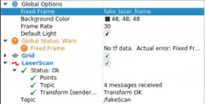
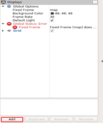
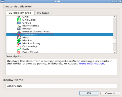
2.Add a LaserScan visualization.
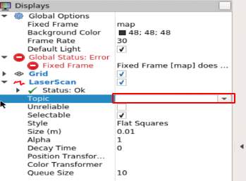
3. The visualization is not showing due to some problems with the frame.
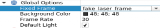
4. Let’s change the fixed frame to the fake_laser_frame
Now everything looks fine but the laserscan still not showing.
How come?
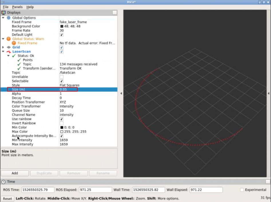
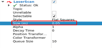
It turns out, in this particular example, it’s not showing simply because the size of the visualization is too small to be seen. Let’s change the size.
Takeaway Today:
You can check if one topic is publishing correctly by typing rostopic echo /TOPICNAME
If you want to check the topic in RViz, remember to select correct topic type, correct frame and choose a proper size!
If you want to learn more about ROS, we have ROS courses for different levels available in Robot Ignite Academy. You can preview any of them for free.
Edit by Tony Huang
[irp posts=”7406″ name=”ROS Q&A | How to merge data from two different lasers”]
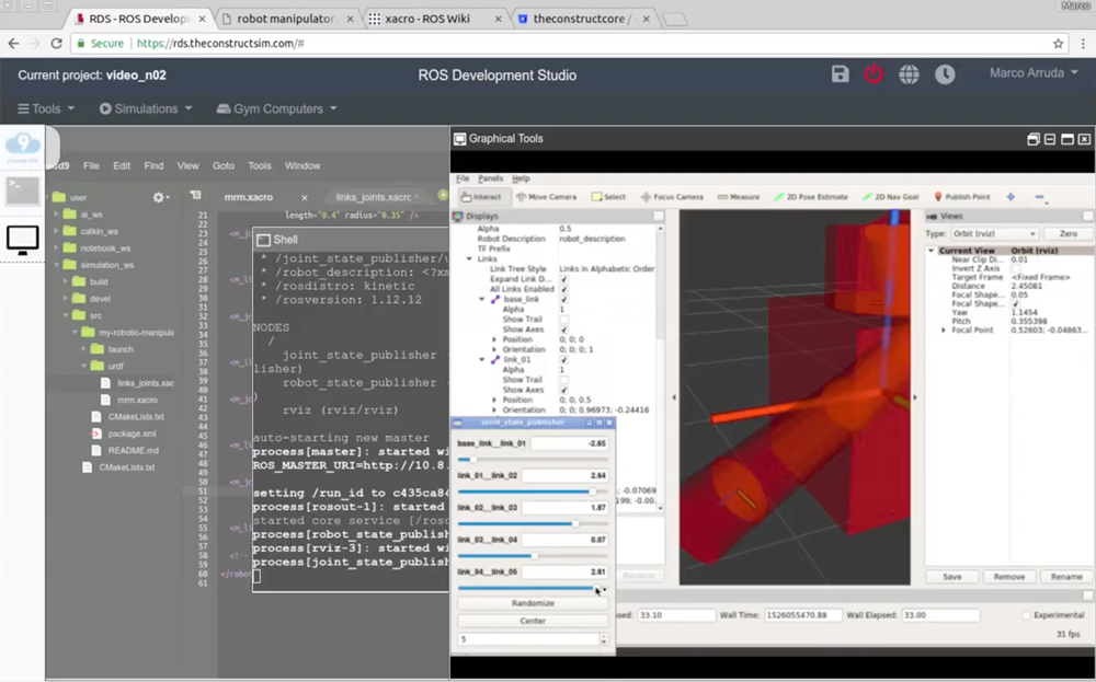
In this video we’ll improve our URDF code of the robotic manipulator using XACRO. From the URDF model, finish the robot, creating all joints and links and visualize it using RViz. Up to the end of the video, we will have the model finished, a launch file to visualize it and a RViz and some MACROs to help you in the development of the robot.
In this video we are going to see how to write robot Poses into a file. This will allow you to keep track of the different positions that a mobile robot is in while it is moving.
▸ Get the code of the video by clicking on this link: https://goo.gl/DBdKoz (You need an account on RDS. Once you click on the link, the whole code will appear on your RDS account ready to use)
Follow these steps to reproduce the project as shown in the video
Create a new project. Choose a informative name and add some description in the description field. (for this tutorial we are using project name poses_to_file)
Open the project. This will being you to the RDS environment with two menu options Tools and Simulations
Start an IDE by selecting IDE option from the Tools. IDE is a very useful tool, it lets you navigate and edit files/directories. Try navigating around and verify that the directory layout of the project is as shown below:
Note that we use simulation_ws directory to contain all files related to simulations.
Those files not related to simulations will go to catkin_ws (like python scripts, launch files etc)
Step 2
We will create a new catkin project inside the catkin_ws/src directory
$ cd catkin_ws/src catkin_create_pkg poses_to_file rospy
Next we will create a python script to write the poses to the file. We will create this script inside the newly created project.
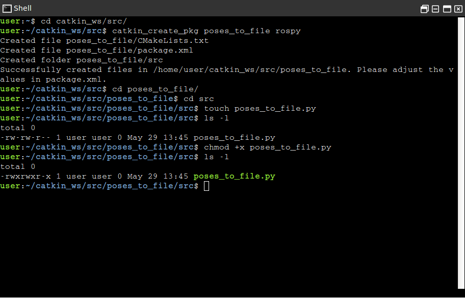
$ cd poses_to_file/src touch poses_to_file.py
We have now created a empty script file named poses_to_file.py. We also need to make it executable. Use following commands to make it executable
$ chmod +x poses_to_file.py
Verify the permission by using the listing unix command
$ ls -l
Step 3
We will now write the program inside the python script.
The script contains class named SavePoses with following member functions
__init__
sub_callback
write_to_file
+
The role of __init__ function would be to initialize a Pose type (_pose), a dictionary type (poses_dict) to hold Poses. We will subscribe to the /odom topic as well.
Function sub_callback is the callback for the subscriber we create in the __init__. Inside this callback function we receive the current pose and copy it inside variable _pose.
The function write_to_file is tasked with following:
initializing dictionary keys pose1, pose2 and pose3
open a file in write mode
iterate through the keys of dictionary and write a formatted string containing values corresponding to the keys.
The complete code is as follows:
#! /usr/bin/env python

import rospy
from nav_msgs.msg import Odometry
from geometry_msgs.msg import Pose
import time


class SavePoses(object):
    def __init__(self):

        self._pose = Pose()
        self.poses_dict = {"pose1":self._pose, "pose2":self._pose, "pose3":self._pose}
        self._pose_sub = rospy.Subscriber('/odom', Odometry , self.sub_callback)
        self.write_to_file()

    def sub_callback(self, msg):

        self._pose = msg.pose.pose

    def write_to_file(self):

        time.sleep(5)
        self.poses_dict["pose1"] = self._pose
        rospy.loginfo("Written pose1")
        time.sleep(5)
        self.poses_dict["pose2"] = self._pose
        rospy.loginfo("Written pose2")
        time.sleep(5)
        self.poses_dict["pose3"] = self._pose
        rospy.loginfo("Written pose3")


        with open('poses.txt', 'w') as file:

            for key, value in self.poses_dict.iteritems():
                if value:
                    file.write(str(key) + ':\n----------\n' + str(value) + '\n===========\n')

        rospy.loginfo("Written all Poses to poses.txt file")


if __name__ == "__main__":
    rospy.init_node('spot_recorder', log_level=rospy.INFO)
    save_spots_object = SavePoses()
    #rospy.spin() # mantain the service open.
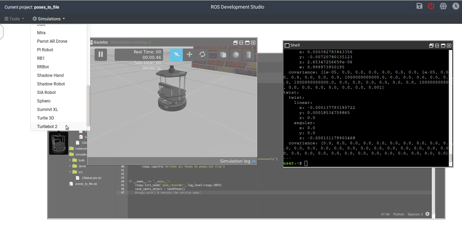
Before we run this script we need to start a simulation that will create a `/odom` topic. This topic will publish the odometry messages. Use the Simulations menu and select Turtlebot2 to start a simulation. Once the simulation is running you will see something like follows:
Now we can run the script with following command
$ rosrun poses_to_file poses_to_file.py
Let the script finish writing the poses to file. You will find a new file called poses.txt inside the src directory. This file will contain the poses as expected.
Thats about it. Enjoy learning ROS with Robot Ignite Academy.
In this video we are going to see how to convert a PointCloud into a laser scan. You can use later that laserscan as a lidar for robot navigation. This allows to do navigation with a very cheap sensor.
▸ Get the code of the video by clicking on this link: https://goo.gl/z3fNCs (You need an account on ROSDS. Once you click on the link, the whole code will appear on your ROSDS account ready to use. Watch the video for additional instructions)
Below are the step by step instructions for creating the project on ROSDS.
NOTE: if you are not using the ROSDS and you are using your local ROS installation, then you need to have installed the ROS package PointCloud To LaserScan (find the link below in the related links section).
Step 1
Head to Robot Development Studio and create a new project
Provide a suitable project name and some useful description (we are using the name “pointcloud to laser”)
Open the project (this will take few seconds)
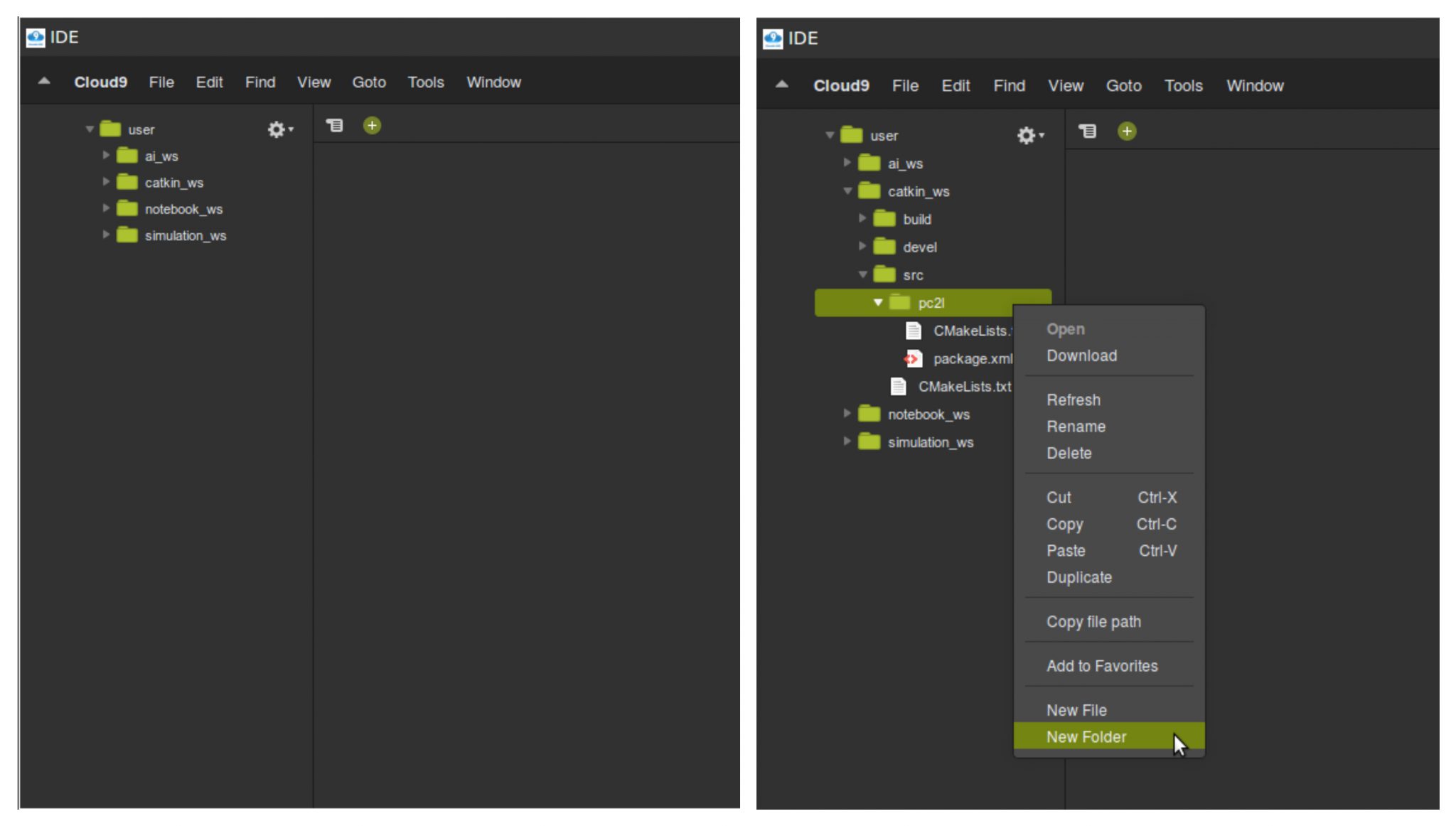
Once the project is loaded run the IDE from the tools menu. Also verify that the inital directory structure should look like following
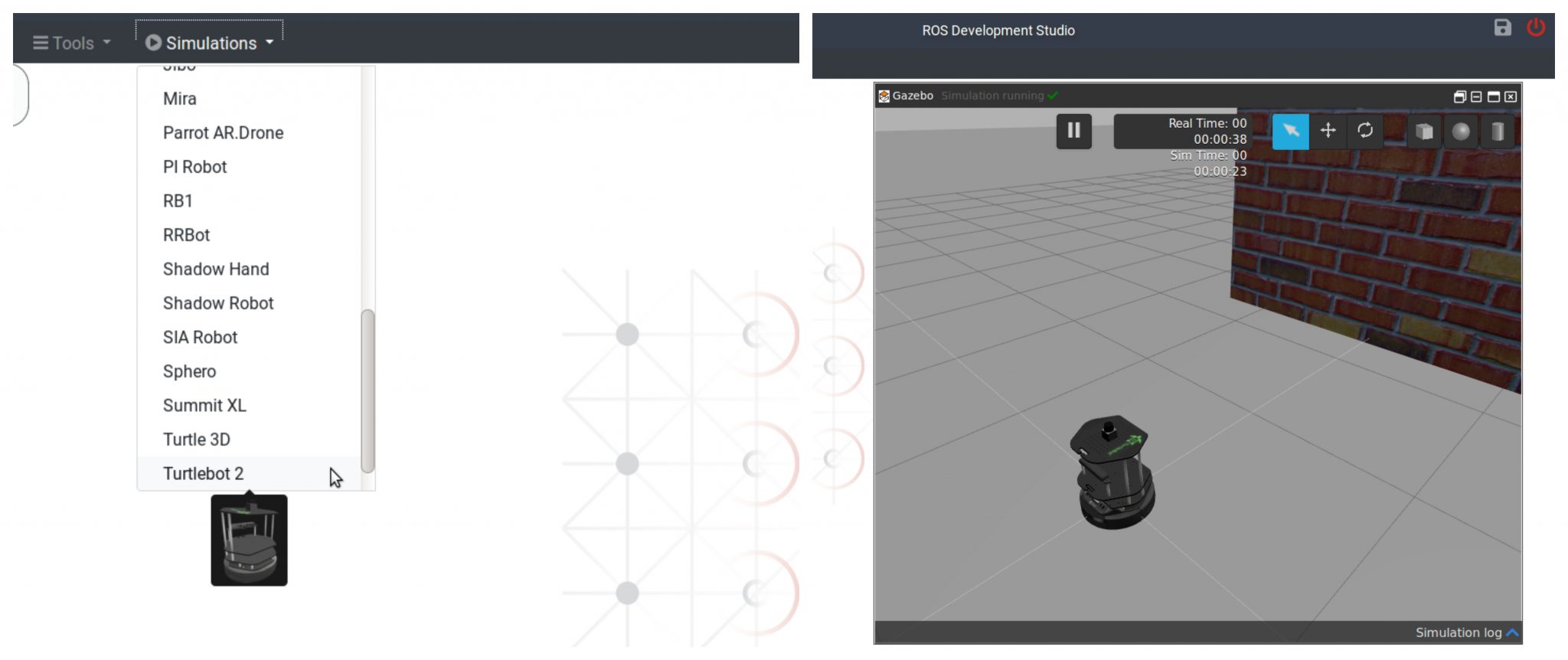
Simulate a turtlebot2 by choosing Turtlebot 2 option in the Simulation menu.
Next we will create a package pc2l (stands for PointCloud2Laser). Open a shell, browse to ~/catkin_ws/src directory and create a package with name pc2l
$ cd ~/catkin_ws/src
$ catkin_create_pkg pc2l
Further, we need to create a launch file that will create a node to do the conversion of pointcloud data to laser scan data (using pointcloud_to_laserscan library). We will create a launch directory then a launch file by name start.launch. We can use the IDE tool to achieve the same
Create a new file (inside the launch folder) with name start.launch and input the following contents (Note: The pointcloud_to_laserscan library needs to be installed in the system)
<launch>
    <node pkg="pointcloud_to_laserscan" type="pointcloud_to_laserscan_node" name="pointcloud_to_laserscan">
      <remap from="cloud_in" to="/camera/depth/points"/>
      <remap from="scan" to="/camera/scan" />
      <rosparam>
        target_frame: camera_link
        transform_tolerance: 0.01
        min_height: 0.0
        max_height: 1.0

        angle_min: -1.5708
        angle_max: 1.5708
        angle_increment: 0.0087
        scan_time: 0.3333
        range_min: 0.45
        range_max: 4.0
        use_inf: true

        #concurrency_level affects number of pc queued for processing and the number of threadsused
        # 0: Detect number of cores
        # 1: Single threaded
        # 2: inf : Parallelism level
        concurrency_level: 1
      </rosparam>
    </node>
</launch>
This **launch file** set’s up various parameters which are briefed below:
cloud_in : This argument contains the name of the topic that is publishing the pointcloud data. scan : This argument contains topic name (created by pointcloud_to_laserscan) that contains the converted scan data. target_frame : Tells the frame of reference for laser scan min and max height : Define the height range which will be taken into account while converting the pointcloud min and max angle : Define the range of angle over which laser scan data is composed about angle increment : The step increase in angle between conscuting scans scan time : The scan time is the interval between publishing two scans min and max range : This arguments defines the range of distance captured in the scans use inf : A point detected further than max range is encoded as inf point concurrency : This parameters controls how much cpu you want to allocate to the pointcloud to laser scan processing
Step 3
Now we can run the launch file, visualize the data (laser scan) and compare the pointcloud converted laser scan data with laser scan data provided by a laser scanner mounted on the robot.
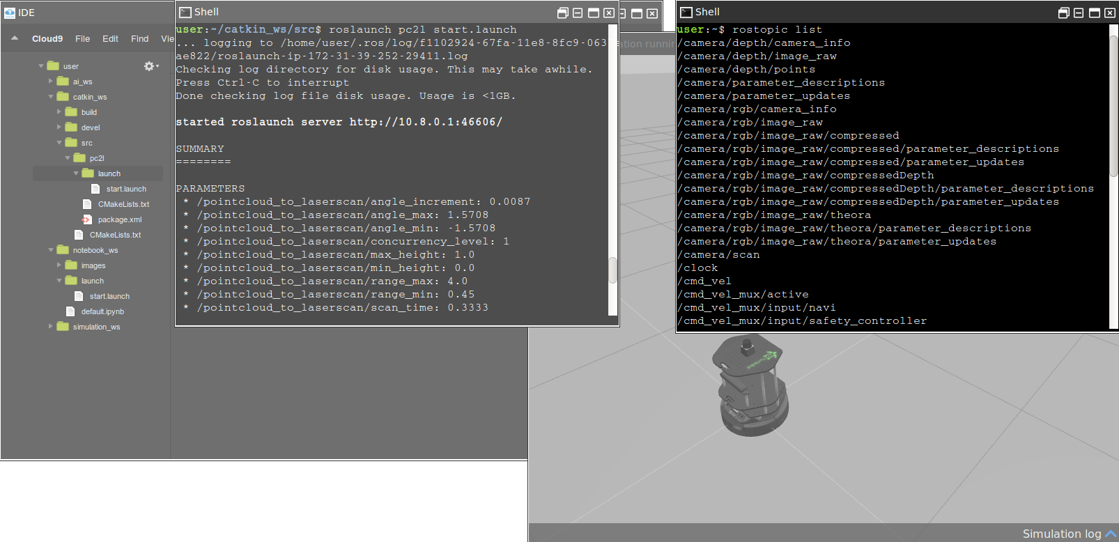
In the Shell type the following command to run the launch file
$ roslaunchg pc2l start.launch
This command will start a new topic with name /camera/scan. To verify start a new Shell and run the command
$ rostopic list
To visualize the data published over the /camera/scan topic we will run rviz In the shell, type the following command
$ rosrun rviz rviz
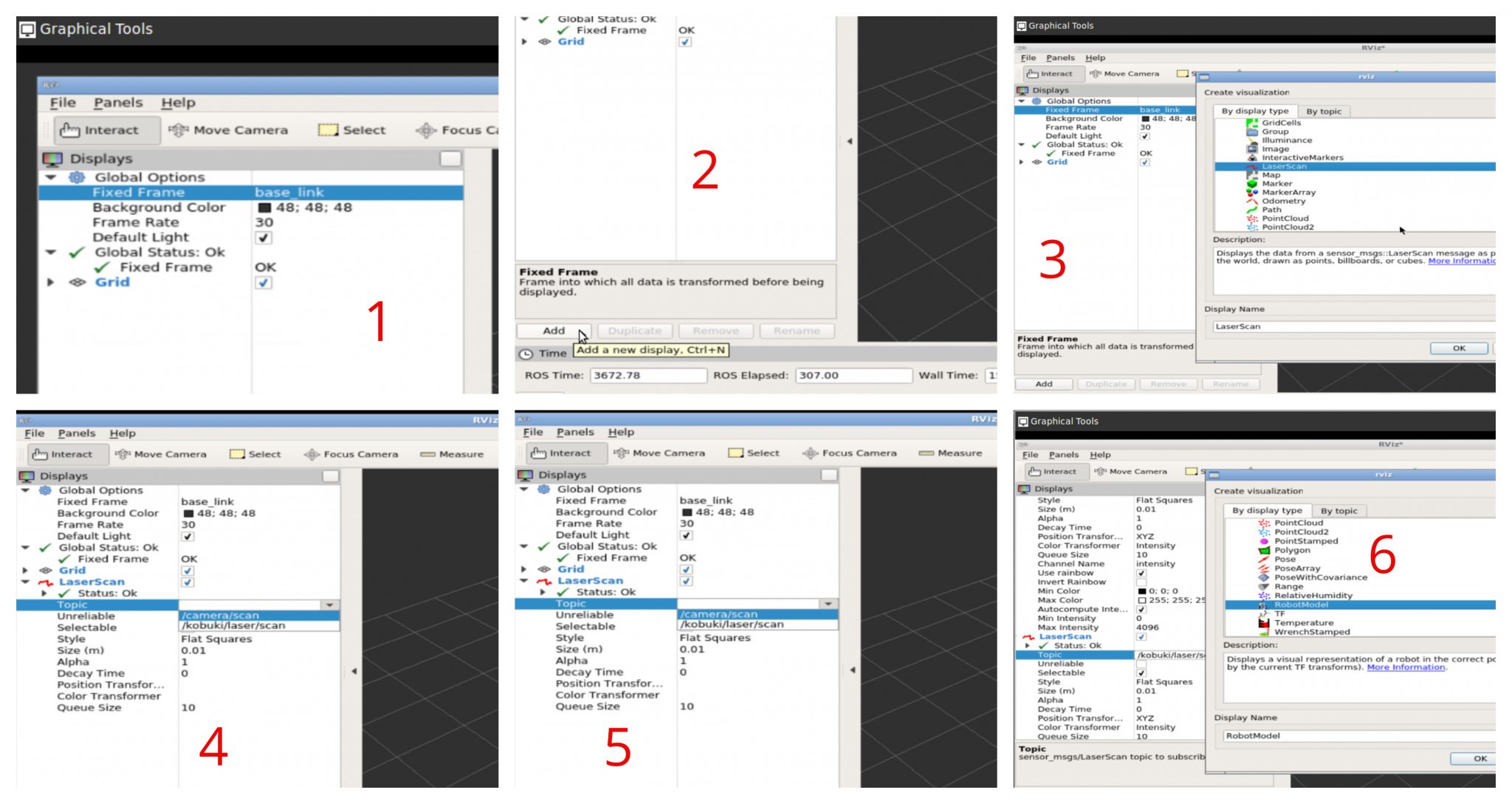
To see the rviz window we require a Graphical Tool
Once the rviz loads we will fix the errors by choosing appropriate value for Fixed Frame parameter. Then we will add following new displays
Laser display 1 : We will select the topic /camera/scan
Laser display 2 : We will select the topic /kobuki/laser/scan
Robot Model : We will add a robot model to visualize a turtlebot inside the rviz window
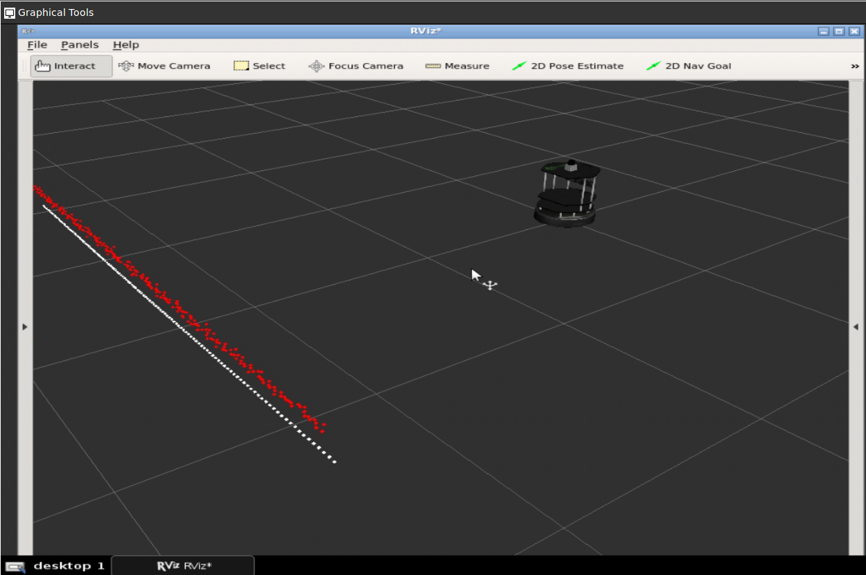
After we are done with all settings we will see the following
There are two laser scans one is from the /camera/scan (white colored) and the other is from /kobuki/laser/scan. We are done at this point.
// RELATED LINKS
▸ Point Cloud To LaserScan ROS package: http://wiki.ros.org/pointcloud_to_laserscan ▸ ROS Development Studio: https://goo.gl/tnjCD5 ▸ Robot Ignite Academy: https://goo.gl/8EhkWn ▸ ROS Navigation in 5 days online course: https://goo.gl/mkRYiR
![[ROS Q&A] 124 – Range sensor does not detect obstacles in Gazebo](https://www.theconstruct.ai/wp-content/uploads/2018/05/Range-sensor-does-not-detect-obstacles-in-Gazebo.png)
![[ROS Q&A] 123 – Roslaunch can’t locate node, but rosrun works fine](https://www.theconstruct.ai/wp-content/uploads/2018/05/ROS-QA-123-Why-roslaunch-cant-locate-node-but-rosrun-works-fine-.png)
![[ROS Q&A] 122 – How to show laser data on Rviz](https://www.theconstruct.ai/wp-content/uploads/2018/05/laser_data_on_Rviz_capture.png)